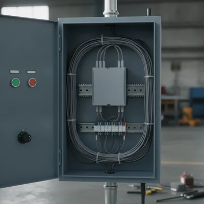
INVT GD20 & GD200A Control Terminal Wiring: Fast, Error-Free Setup
Moving an INVT GD20 or GD200A VFD from keypad buttons to remote switches, pushbuttons, an external potentiometer, or preset multi-step speeds takes less than 10 minutes once you avoid three factory traps. First, terminal S2 ships configured as Forward Jog (P05.02 = 4), not Reverse. Second, Frequency B channel P00.07 defaults to 2 (AI2), so the drive blocks you from saving P00.06 = 2 until you free up P00.07. Third, default NPN internal logic expects dry contacts to close to COM with the U-shaped jumper fitted between +24V and PW.
Quick commissioning summary: 1) Reset defaults via P00.18 = 1 (GD200A manual, p. 47). 2) Enable terminal run commands with P00.01 = 1 (p. 41); for a 2-wire FWD/REV selector set P05.01 = 1, P05.02 = 2, P05.13 = 0 (pp. 63, 65). 3) For 3-wire Start (NO) + Stop (NC) pushbuttons set P05.02 = 3 and P05.13 = 2 (or 3 for a separate Reverse pushbutton, p. 66). 4) For an external 10 kOhm potentiometer on +10V / AI2 / GND, first change P00.07 = 0 (or 4), then set P00.06 = 2 and verify jumper J4 is in the voltage position (pp. 31, 42). 5) For multi-step speeds set P00.06 = 6, terminal functions 16–19 in P05, and speeds in P10.02–P10.32 (pp. 43, 64, 92–94).
1. Terminal Block Differences: INVT GD20 vs GD200A
Both the compact GD20 and the general-purpose GD200A share the same parameter structure across groups P00, P05, and P10. Programming steps match closely, while the physical terminal count differs — an important factor when planning a panel that combines 3-wire pushbuttons with multiple preset speeds.
| Interface | INVT GD20 (Compact) | INVT GD200A (General Purpose) | GD200A Manual Ref |
|---|---|---|---|
| Digital inputs (DI) | S1–S4 + high-speed HDIA / HDI (up to 5 DI) | S1–S8 + HDI (up to 9 DI; switch HDI to DI via P05.00 = 1) | pp. 30–32, 63 |
| Analog inputs (AI) | Built-in keypad pot (AI1) + external AI2 (0–10 V / 0–20 mA) and AI3 (frame-dependent) | AI1 (keypad pot only on 015G/018P ≤15 kW; absent on 018G/022P and up) + AI2 (0–10 V / 0–20 mA via J4) + AI3 (−10…+10 V) | pp. 31, 36, 42, 68 |
| Control power & NPN/PNP | +24V, PW, COM (+24V–PW tag for NPN) | +24V (max 200 mA), PW (12–30 V), COM; factory U-shaped tags on +24V–PW (NPN) and COM–CME | pp. 31–33 |
| Relay & analog outputs | 1–2 relays (RO1/RO2) + AO1 | RO1 & RO2 (3 A / AC 250 V, 1 A / DC 30 V), AO1 / AO2 (jumpers J1/J2), Y1 / HDO | pp. 31–32 |
If you have not entered motor nameplate data or wired main power yet, start with our INVT VFD setup and power wiring guide. For retrofit projects comparing compact drives, see INVT GD20 vs Veichi AC10 interchangeability.
2. Pre-Wiring Prep: Factory Reset (P00.18) and NPN/PNP Selection
Whenever a drive comes off a test bench or another machine, restore factory defaults before landing control wires so leftover terminal assignments in group P05 cannot trigger unexpected starts.
- Factory reset (P00.18, p. 47): open
P00.18, set 1, and press DATA/ENT. The code automatically returns to0after completion. Note the manual warning: resetting also clears the user password. Value2clears fault history, and3locks the keypad (all codes except P00.18 become read-only). - U-shaped contact tag (+24V / PW / COM, pp. 32–33): factory default links +24V to PW for internal-power NPN mode. In this mode, all switches, pushbuttons, and dry relay contacts close terminals S1–S8 to COM. If an external PLC drives the inputs with PNP sourcing outputs (+24 V), move the jumper to COM–PW (internal +24 V) or connect external 0 V to PW.
- Cable routing and shielding: separate control wiring from
R/S/TandU/V/Wpower cables. Always run shielded twisted pair for an external potentiometer and ground the shield at PE on the VFD end only.
3. Terminal Run Commands (P00.01) and 2-Wire Control (P05.13 = 0 or 1)
Parameter P00.01 selects the run command channel (GD200A manual, p. 41): 0 = keypad RUN/STOP (LOCAL/REMOT LED off), 1 = external control terminals (LOCAL/REMOT LED flickering), and 2 = RS485 Modbus communication.
Check the factory defaults of P05.01–P05.05 (p. 63): P05.01 = 1 (S1 = Forward), P05.02 = 4 (S2 = Forward Jog — NOT Reverse!), and P05.03 = 7 (S3 = Fault Reset). You must change P05.02 to 2 to get Reverse on S2.
2-Wire Selector Switch: FWD / 0 / REV (P05.13 = 0)
This is the standard layout for conveyors, fans, and machine tools using a maintained 3-position selector switch with two normally open (NO) contact blocks:
- Wire the common side of both NO contact blocks to COM (default NPN mode with
+24V–PWjumpered). - Land the Forward contact on S1 and the Reverse contact on S2.
- Set P00.01 = 1 (terminal run), P05.01 = 1 (S1 = Forward), P05.02 = 2 (S2 = Reverse), and P05.13 = 0 (2-wire control 1, p. 65).
Truth table for P05.13 = 0 (p. 65): both OFF = Stop; S1 ON = Forward; S2 ON = Reverse; both ON = Hold on. If your panel uses one Run/Stop switch on S1 and a separate Direction switch on S2, set P05.13 = 1 (2-wire control 2, pp. 65–66): S1 acts strictly as Run Enable (OFF = always Stop), while S2 sets direction (OFF = Forward, ON = Reverse).
4. 3-Wire Momentary Pushbutton Control (P05.13 = 2 and 3)
For panel doors fitted with momentary pushbuttons — green START (NO) and red STOP (NC) — 2-wire mode will drop out as soon as you release the button. INVT GD20/GD200A provides two latched 3-wire modes under P05.13 (p. 66).
| P05.13 Mode | Panel Operators | Wiring to COM (NPN) | Required Parameters |
|---|---|---|---|
| P05.13 = 2 (3-wire control 1) | Green SB1 START (NO) + red SB2 STOP (NC) + optional K REV selector (NO) | SB1 → S1 (FWD); SB2 (NC!) → S2 (SIn); K → S3 (REV) | P00.01 = 1, P05.01 = 1, P05.02 = 3 (3-wire), P05.03 = 2 (if reversing), P05.13 = 2 |
| P05.13 = 3 (3-wire control 2) | Three momentary buttons: SB1 FWD (NO) + SB2 STOP (NC) + SB3 REV (NO) | SB1 → S1 (FWD); SB2 (NC!) → S2 (SIn); SB3 → S3 (REV) | P00.01 = 1, P05.01 = 1, P05.02 = 3 (3-wire), P05.03 = 2, P05.13 = 3 |
Mandatory rule for both 3-wire modes: the SB2 STOP button wired to the terminal assigned function 3 (S2 above) must be a normally closed (NC) contact. While S2–COM stays closed, the drive is enabled (SIn = ON); pulsing SB1 starts the motor, and pressing SB2 opens S2–COM to decelerate to a stop (p. 66). Wiring an NO contact to S2 prevents the drive from starting at all.
5. External Potentiometer on +10V / AI2 / GND and the P00.07 Trap
Mount a linear 5–10 kOhm potentiometer on the cabinet door for smooth remote speed control (10 kOhm is the field standard; AI2 voltage input impedance is 20 kOhm, GD200A manual, p. 31).
Wiring and Jumper J4
- One outer leg of potentiometer → +10V (internal +10 V reference supply).
- Center wiper leg → AI2 (0–10 V analog input).
- Other outer leg → GND (+10 V reference zero — do not confuse with COM!).
- Jumper J4 on GD200A control board (p. 31): selects AI2 between voltage
0–10 V(20 kOhm) and current0/4–20 mA(500 Ohm). Keep J4 in the V (voltage) position for a potentiometer.
If turning the knob clockwise lowers the frequency instead of raising it, simply swap the outer +10V and GND leads on the potentiometer while leaving the center AI2 wiper intact.
Why P00.06 = 2 Fails at First: Clearing the P00.07 Default Conflict
The GD200A manual (p. 42) states explicitly: «Frequency A and frequency B cannot use the same frequency setting mode.» Out of the box, P00.06 = 0 (keypad P00.10) while P00.07 = 2 (already bound to AI2!). Attempting to set P00.06 = 2 immediately will be rejected.
Correct sequence:
- Open P00.07 (Frequency B) and change it from
2to any unused source such as 0 (keypad) or 4 (HDI pulse). - Open P00.06 (Frequency A) and set it to 2 (AI2 external analog).
- Confirm P00.09 = 0 (Frequency A active, p. 44).
- Verify live voltage in monitor P17.20 (p. 103): turning the dial end-to-end should sweep smoothly from
0.00 Vto10.00 V.
6. Scaling Analog Input AI2 (P05.37–P05.41)
By default, 0 V equals 0 Hz and 10 V equals maximum frequency P00.03 (typically 50 Hz). To enforce a minimum speed floor (for example 20 Hz at the bottom of the dial), remove edge deadband, or damp noisy readings, adjust P05.37–P05.41 (p. 69).
| Parameter | Name (Manual p. 69) | Default | Range | Practical Use |
|---|---|---|---|---|
| P05.37 | Lower limit of AI2 | 0.00 V | 0.00 V – P05.39 | Set 0.10–0.20 V if noise keeps the drive creeping at 0.3–0.5 Hz at zero dial |
| P05.38 | Lower limit setting % | 0.0% | −100.0% – 100.0% | Set 40.0% (with P00.03 = 50 Hz) so full counter-clockwise gives 20 Hz |
| P05.39 | Upper limit of AI2 | 10.00 V | P05.37 – 10.00 V | Lower to 9.70–9.80 V if cable voltage drop caps speed at 48.5 Hz |
| P05.40 | Upper limit setting % | 100.0% | −100.0% – 100.0% | 100.0% = P00.03; inverting P05.38=100% / P05.40=0% reverses slope |
| P05.41 | AI2 input filter time | 0.100 s | 0.000 – 10.000 s | Raise to 0.300–0.500 s to steady jittery frequency from EMI or a worn pot |
If you need closed-loop pressure control via a 4–20 mA transducer on AI2 rather than manual speed, see our INVT pump PID and sleep mode setup guide.
7. Multi-Step Speed Mode: P00.06 = 6, Terminals 16–19 & Group P10
Multi-step speed control switches between up to 16 preset frequencies via four digital inputs driven by selector switches, relays, or PLC outputs — ideal for woodworking machinery, conveyors, drying ovens, and multi-speed ventilation.
Per the GD200A manual (pp. 43, 64, 92–94), configuration takes three steps:
- Select multi-step frequency source: set P00.06 = 6 (p. 43). Note from p. 93: even when
P00.06is set to potentiometer or keypad, closing any terminal assigned functions16–19overrides keypad, analog, HDI, PLC, and Modbus speed references. When all multi-step terminals are OFF, the drive reverts toP00.06(or runs Speed 0P10.02ifP00.06 = 6). - Assign digital inputs in P05 (p. 64): set free inputs to 16 (Multi-step terminal 1), 17 (terminal 2), 18 (terminal 3), and 19 (terminal 4). On GD200A with 2-wire run on S1/S2, assign
P05.03 = 16(S3),P05.04 = 17(S4),P05.05 = 18(S5),P05.06 = 19(S6). On compact GD20 (S1–S4 + HDI), S3, S4, and HDI (withP05.00 = 1, p. 63) give 3 binary bits = 8 preset speeds (Speed 0–7). - Program preset speeds in P10 (pp. 92–94): even-numbered codes
P10.02, P10.04, P10.06 ... P10.32set Speed 0–15 as a percentage of P00.03 (range−100.0% to +100.0%; negative values run in reverse!). Odd-numbered codesP10.03, P10.05 ... P10.33are step durations used only in Simple PLC mode (P00.06 = 5).
| Step | Terminal 1 (16) | Terminal 2 (17) | Terminal 3 (18) | Terminal 4 (19) | P10 Code | Example (P00.03 = 50 Hz) |
|---|---|---|---|---|---|---|
| Speed 0 | OFF | OFF | OFF | OFF | P10.02 | 20.0% → 10 Hz |
| Speed 1 | ON | OFF | OFF | OFF | P10.04 | 30.0% → 15 Hz |
| Speed 2 | OFF | ON | OFF | OFF | P10.06 | 50.0% → 25 Hz |
| Speed 3 | ON | ON | OFF | OFF | P10.08 | 70.0% → 35 Hz |
| Speed 4 | OFF | OFF | ON | OFF | P10.10 | 80.0% → 40 Hz |
| Speed 5 | ON | OFF | ON | OFF | P10.12 | 90.0% → 45 Hz |
| Speed 6 | OFF | ON | ON | OFF | P10.14 | 100.0% → 50 Hz |
| Speed 7 | ON | ON | ON | OFF | P10.16 | −50.0% → 25 Hz reverse |
| Speed 8–15 | comb. | comb. | comb. | ON | P10.18–P10.32 | up to 16 steps (GD200A / 4 DI) |
8. Common Field Mistakes and Live Diagnostics in Group P17
Before rewiring a silent panel, read live I/O diagnostics in monitoring group P17:
- Digital input monitor P17.12 (p. 102): displays the real-time bitmask of S1–S8/HDI. Toggle a switch and watch the value change; if nothing moves, check the
+24V–PWU-tag and make sure switches close toCOM, notGND. - Analog AI2 voltage monitor P17.20 (p. 103): if stuck at
0.00 Vor10.00 V, measure+10V–GNDwith a multimeter and verify jumper J4 is set to V. - YouTube caption typos to watch for: some tutorial overlays mistakenly label
P00.06as 'Lower limit frequency' (lower limit is actually P00.05, p. 42) or confuseP00.06 = 1(keypad AI1 pot) withP00.06 = 2(external AI2 terminal). Always verify against the manual table. - Contact bounce or EMI: if relays or long control runs cause false triggers on S1–S8, raise P05.11 debounce filter time from
0.010 sto0.050–0.100 s(p. 65). If a fault code appears on the display, consult our INVT VFD error codes diagnostic guide.
9. Sources & Technical Verification
- Official manufacturer documentation: INVT Goodrive200A Operation Manual (EN) (pp. 30–33, 36, 41–44, 47, 63–69, 92–94, 102–103) and INVT Goodrive200A Manual (UK).
- Field YouTube references: Nice Electronics — INVT GD20 & GD200A VFD Programming and Control Terminal Wiring; plc247 Automation — INVT GD20 Setup Tutorial; 2AD TECH — VFD INVT-GD20 Basic Programming Inverter.
Every parameter number, terminal assignment, jumper function, and truth table has been verified against official INVT documentation. Keep in mind the DI count difference between GD20 and GD200A and that built-in keypad potentiometer AI1 is only present on 15 kW (015G/018P) and smaller frames.
INVT Drives and Panel Accessories
In our catalog (in stock and to order), you will find compact INVT GD20 0.75 kW 220V, GD20 1.5 kW 220V, GD20 2.2 kW 220V, GD20 2.2 kW 380V, and general-purpose INVT GD200A 1.5 kW 380V and GD200A 2.2 kW 380V drives. Browse the full INVT VFD catalog along with remote keypads, filters, and wiring accessories in VFD options and accessories.