Configuring INVT VFD for Constant Water Pressure: Step-by-Step Guide
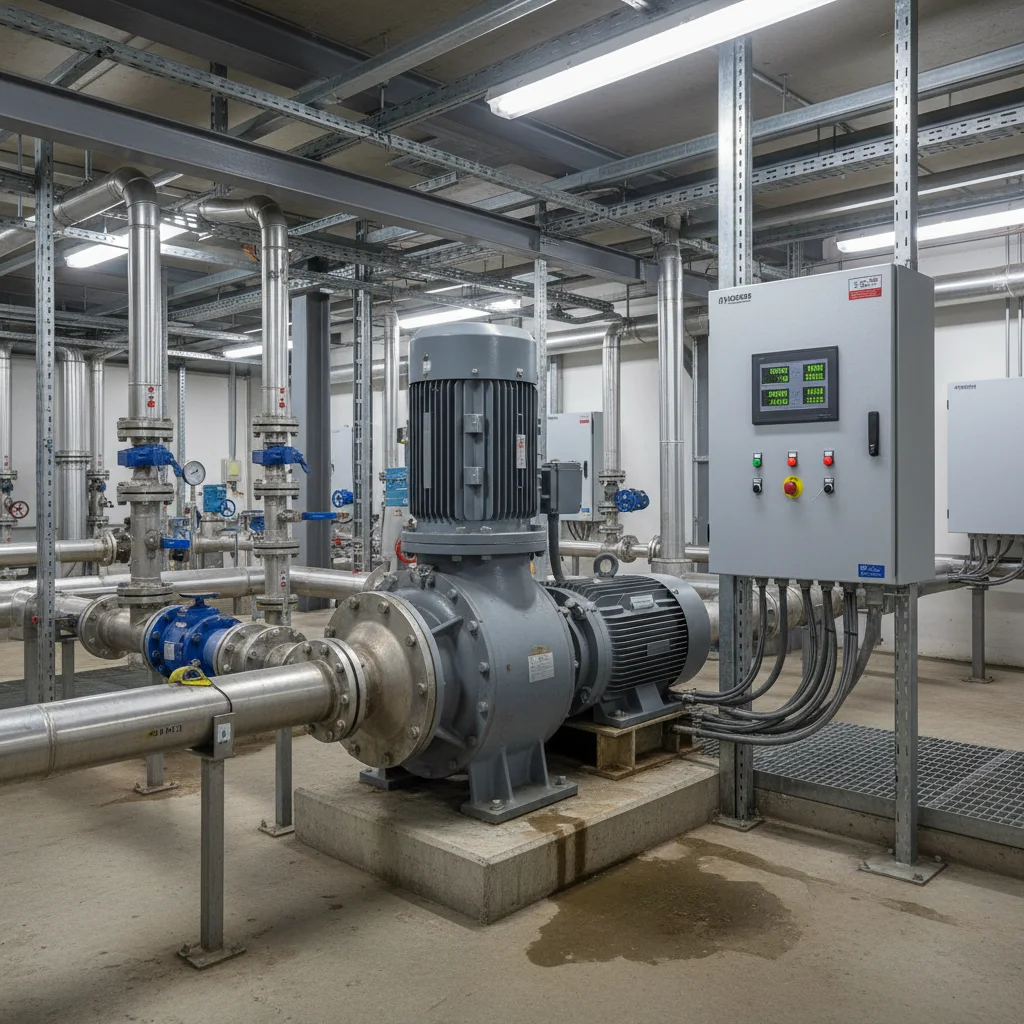
Maintaining stable pressure in a water pipeline saves pump life and protects pipes. An INVT variable frequency drive does this automatically. At our Kyiv warehouse, we select Goodrive GD10, GD20, or GD200A series drives for these tasks daily. Whether for a deep well or industrial water supply, the configuration logic remains identical. For assembly, you will need the VFD, a 4-20mA pressure sensor, a check valve, and an expansion tank up to 24 liters. Below are ready-made parameters and wiring diagrams verified by our engineers in dozens of installations.
Wiring a 4-20mA Pressure Sensor to an INVT VFD
For pressure feedback, use an industrial sensor with a 4-20mA output. The current loop is resistant to noise and operates up to 150 meters from the control panel. We recommend sensors with a 0-10 bar scale. This fully covers the needs of private homes and small production facilities. Connecting a two-wire sensor to an INVT drive is straightforward.
The terminal wiring diagram is as follows:
- Sensor Power (+24V): Connect the +24V terminal on the VFD board to the positive contact of the sensor (usually Pin 1 or marked L+).
- Analog Signal (AI2): Connect the negative contact of the sensor (Signal / Pin 2) to the analog input AI2 of the frequency converter.
- Common Wire (COM): Unlike 3-wire setups, you do not need to run a separate minus to COM because the current returns through the analog input.
- Cable Shield: Be sure to ground the shield of the signal cable on the VFD side to the PE terminal. Leave the shield isolated on the sensor side.
After installation, check the control board. The AI2 analog input switch is located there. By default, it may be set to the voltage (V) position. You must move it to the current (I or mA) position. Without this, the VFD will not recognize the 4-20mA signal and will trigger a fault due to a lack of feedback.
PID Control Parameters (Group P09) for Constant Pressure Maintenance
The built-in PID controller of the INVT VFD compares the sensor signal with the target value and smoothly adjusts the pump speed. All settings for this loop are located in parameter group P09. We have collected verified values suitable for 95% of domestic and industrial pump stations.
| Code | Parameter Name | Value | Technical Explanation |
|---|---|---|---|
| P09.00 | PID target source | 0 | Pressure target set using the buttons on the control panel via parameter P09.01. |
| P09.01 | PID digital target value | 30.0–40.0% | Target pressure as a percentage of the sensor scale. For a 10 bar sensor, 30% equals 3.0 bar of system pressure. |
| P09.02 | PID feedback source | 1 | The VFD takes the signal from analog input AI2 (our 4-20mA sensor). |
| P09.04 | Proportional gain (Kp1) | 1.5 | Determines response speed. Too high a value will cause water hammer and pressure oscillations. |
| P09.05 | Integral time (Ti1) | 2.5s | Smooths system operation. Too short a time will make the pump jerk, while too long will lead to slow pressure buildup. |
In our experience, starting the system is best done with a proportional gain of 1.5 and an integral time of 2.5 seconds. If the system pressure takes too long to stabilize when valves open, first try increasing the integral time to 4.0 seconds. Only after that should you adjust the proportional gain. Do not set Kp1 above 3.0, or pressure waves will damage the threaded connections.
Configuring Sleep and Wake-up Modes
Sleep mode stops the pump when there is no water usage. This prevents water from overheating inside the pump casing and saves electricity. Without correct sleep settings, the motor will run indefinitely at minimum speed, wasting bearing life. In INVT inverters, this logic is configured using parameters in group P01.
- Sleep frequency threshold (P01.19): Set between 32.0–35.0 Hz. This is the speed where the pump spins against a closed valve but creates no actual flow. For deep well pumps (40+ meters), the sleep threshold is usually higher, around 36.0–38.0 Hz.
- Sleep delay time (P01.20): Set from 5 to 10 seconds. The VFD waits for this duration after the operating frequency falls below the sleep threshold. This prevents the pump from shutting down during brief valve closures.
- Wake-up threshold (P01.21): Determines the pressure drop needed for startup. We recommend setting this between 10.0–15.0%. For example, if the target pressure is 3.0 bar, the drive will wake up when the pressure drops to 2.7–2.55 bar.
- Wake-up delay time (P01.22): Set to 2–3 seconds. This delay before starting after a pressure drop protects the system from reacting to small water pulsations.
If the pump does not sleep when valves are closed, slowly raise the sleep frequency threshold (P01.19) in 0.5 Hz steps. However, do not set it too high (e.g., to 42 Hz). Otherwise, the pump will shut off even during minor water usage, causing the system to cycle repeatedly.
Dry-Run Protection Configuration via S3/S4 Digital Inputs
Operating without water instantly damages pump diffusers and impellers. An INVT VFD allows you to implement reliable protection using multi-functional digital inputs S3 or S4. You can connect an external float switch, dry-run sensor, or pressure switch to these terminals.
To configure the protection, follow these steps:
- Physical Connection: Connect the contacts of the float or dry-run switch between digital input S3 (or S4) and the common wire COM of the frequency converter.
- S3 Terminal Function (P05.03): Set to 12 (external fault, normally open contact) or 13 (external fault, normally closed contact). If using a float switch that opens when water disappears, set this to 13.
- S4 Terminal Function (P05.04): If the sensor is connected to S4, set parameter P05.04 to 12 or 13 in the same way.
When the water level in the well or tank drops, the sensor will trigger, and the VFD will immediately stop the motor, showing an external fault error on the screen. To reset the fault after the well refills, press the RST button on the control panel or configure the automatic reset time.
Sizing and Pre-charging the Expansion Tank (2-24L)
A membrane tank (expansion tank) is a necessary part of a variable frequency pump system. Its purpose is to compensate for tiny water leaks (e.g., a dripping faucet or check valve behavior). Without a tank, even a single dropped drop will cause an instant pressure fall, forcing the VFD to start every minute for a couple of seconds. This will quickly burn out the power relays of the frequency converter.
When installing a membrane tank, follow three rules:
- Minimum Volume: A small tank of 8 to 24 liters is sufficient. Large 100-liter tanks used in classic systems with pressure switches are not needed here. They will only interfere with the quick response of the PID loop.
- Air Pre-charge: Before connecting to the system, measure the air pressure in the empty tank (without water). It must be exactly 60-70% of the target system pressure. For example, if you configured the VFD for a stable 3.0 bar, the tank must have 1.8–2.1 bar of air.
- Installation Location: Mount the tank near the pressure sensor on the outlet manifold. This smooths hydraulic oscillations and improves feedback accuracy.
If the tank membrane ruptures or air escapes, the system will begin to cycle (turn on and off every 5-10 seconds). If you notice this pump behavior with closed valves, replace the membrane or pump up the air with a compressor immediately.
Conclusions and Technical Recommendations
Configuring an INVT VFD allows you to create an automatic water supply station that maintains pressure regardless of the number of open faucets. The key is to correctly mount the 4-20mA sensor, precisely set the sleep parameters, and monitor the air in the expansion tank. At our Kyiv warehouse, we stock INVT frequency converters for all motor types with an official manufacturer warranty. For pump systems, select pump frequency converters in our catalog. If you have a single-phase motor, see the section with single-phase 220V converters. Our experts will help you choose the equipment and configure the parameters for your tasks.