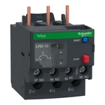
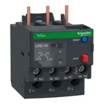
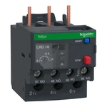
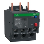
Thermal Overload Relays for Contactors: Operation, Sizing and Connection
Bimetallic thermal overload relays protect three-phase AC induction motors against prolonged thermal overloads, locked rotor conditions, and phase loss. A magnetic contactor only performs start/stop switching without built-in tripping elements. Adding a thermal overload relay directly to the contactor creates a complete motor starter with comprehensive motor protection.
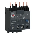
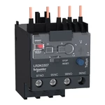
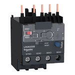
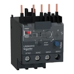
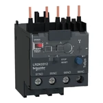
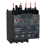
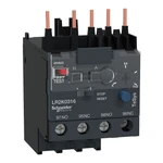
Schneider Electric Thermal Relay Compatibility with Contactors
Thermal overload relays can be direct-mounted beneath the power terminals of matching contactors without wiring, or mounted independently on a DIN rail using an adapter base:
| Relay Series | Compatible Contactors | Current Range, A | Key Features and Specifications |
|---|---|---|---|
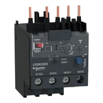
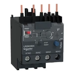
| LR2K | Mini-contactors TeSys K (LC1K, LP1K) | 0.11 ... 16 A | Compact frame for space-critical enclosures. Integrated 1NO + 1NC auxiliary contacts, manual/auto reset selector, Test trip button. |
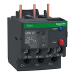
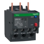
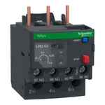
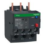
| LRD | Heavy-duty contactors TeSys D (LC1D09 ... LC1D150) | 0.10 ... 140 A | Differential phase failure detection, ambient temperature compensation (-20°C to +60°C), sealable transparent dial cover. |
Current Setting Guidelines
Set the thermal trip dial to the exact motor full-load current ($I_n$) from the motor nameplate according to the line voltage (380V or 220V):
- Normal Duty: Dial set directly to motor full load current ($I_{set} = 1.0 imes I_n$).
- Phase Failure Protection: The differential tripping mechanism accelerates disconnection during single-phasing, protecting motor windings from burnout.
- Integrated Alternative: For combined short-circuit and thermal protection in a single unit, use TeSys GV2 motor circuit breakers. For continuous speed control and energy savings, choose our variable frequency drives (VFDs).