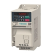
Mitsubishi FR-A800 and FR-A840: terminals, parameters, fault codes
FR-A800 is a Mitsubishi Electric drive family for demanding applications: vector control, encoder feedback and permanent magnet motors. The manual (art. 288856, version D) covers four branches under this name: FR-A820 for 0.4-90 kW, FR-A840 for 0.4-280 kW, FR-A842 for 315-500 kW and FR-A846 for 0.4-132 kW. Below is what you usually need on site: where to connect the power side, how the control terminals are laid out, which parameters to set first and what the fault codes mean.
All figures come from the Russian-language FR-A800 instruction manual hosted on our site: FR-A820_ru.pdf (1006 pages). Factory values of some parameters depend on the output type (FM or CA) and on drive power, and we say so wherever it applies. If your unit differs, go by the rating plate and the manual for your specific batch.
| Branch | Range per the manual |
|---|---|
| FR-A820 (200 V class) | FR-A820-00046(0.4K) ... 04750(90K) |
| FR-A840 (400 V class) | FR-A840-00023(0.4K) ... 06830(280K) |
| FR-A842 | FR-A842-07700(315K) ... 12120(500K) |
| FR-A846 | FR-A846-00023(0.4K) ... 03610(132K) |
FR-A840 models are listed in the FR-A section of the catalog, and the whole brand is on the Mitsubishi Electric variable frequency drives page.
FR-A800 power terminals: what goes where
Mains goes to R/L1, S/L2, T/L3, the motor to U, V, W, and the remaining terminals handle braking, the DC reactor and separate control power. The table below follows the power terminal page of the manual.
| Terminal | Purpose |
|---|---|
| R/L1, S/L2, T/L3 | Mains. When an FR-HC2 or FR-CV power regeneration unit is connected, mains must not be wired to these terminals directly |
| U, V, W | Induction motor or permanent magnet motor |
| R1/L11, S1/L21 | Separate control circuit power. Factory-fitted jumpers connect them to R/L1 and S/L2 |
| P/+, PR | External FR-ABR braking resistor for FR-A820-00630(11K) and smaller and FR-A840-00380(15K) and smaller. Remove the PR-PX jumper first |
| P3, PR | The same for FR-A820-00770(15K)...01250(22K) and FR-A840-00470(18.5K)...01800(55K) |
| P/+, N/- | Brake unit (FR-BU2, FR-BU), FR-CV, MT-RC, FR-HC2 or DC supply |
| P/+, P1 | DC reactor. A jumper is fitted at the factory |
| PR, PX | The built-in brake circuit is active while the PR-PX jumper is in place (only FR-A820-00490(7.5K) and smaller, FR-A840-00250(7.5K) and smaller) |
Three points the manual states directly:
- DC reactor. For FR-A820-03800(75K) and above and FR-A840-02160(75K) and above, connecting it is mandatory. For smaller models, remove the P/+ - P1 jumper only if a reactor is actually installed.
- P3 and P/+ in parallel. When several FR-A820-00770(15K)…01250(22K) or FR-A840-00470(18.5K)…01800(55K) drives are connected in parallel to an FR-CV, FR-HC2 or a DC source, use either P/+ or P3, never both terminals at once.
- Separate control power R1/L11, S1/L21. Remove the R/L1-L11 and S/L2-L21 jumpers if the fault indication must survive a mains cut-off, and when using FR-HC2 or FR-CV. Consumption: 60 VA for FR-A820-00630(11K) and smaller and FR-A840-00380(15K) and smaller, 80 VA for larger models.
We cover the principle of operation and sizing separately: braking resistor: how it works.
Powering the control circuit from an external 24 V
You can feed an external 24 V DC to terminals +24 and SD, so that the panel and parameters stay available without mains. Per the manual: 23-25.5 V, up to 1.4 A. In this mode the panel flashes "EV" (EV signal, Pr.190-Pr.196 = 68 or 168). With external power the Safe Torque Off function does not work, and the power monitors and IPF are inactive. If the 24 V rises slower than 1.5 V/s, E.SAF or E.P24 may appear.
Control terminals: logic, inputs, outputs
The first thing to know about control terminals is the logic type. An FM-type drive works on negative logic out of the box (SINK, common SD), a CA-type on positive logic (SOURCE, common PC). The reference potentials SD, PC, 5 and SE are isolated from each other. Do not ground them, and do not connect SD, PC or SE to terminal 5.
Input signals
| Terminal | Function per the manual |
|---|---|
| STF / STR | Forward / reverse start. If both are on at the same time, a stop command is executed. Input resistance 4.7 kOhm, 21-27 V DC, 4-6 mA |
| STOP | Start self-holding |
| RH, RM, RL | Preset speeds (with REX, up to 15 speeds) |
| JOG | Jog operation; via Pr.291 the terminal can be turned into a pulse input (up to 100 kHz) |
| RT | Second parameter set |
| MRS | Output stop: signal longer than 20 ms |
| RES | Reset: signal longer than 0.1 s, the reset itself takes about 1 s |
| AU | Enables terminal 4 and disables terminal 2 |
| CS | Auto restart after a power failure; not active by default |
| 10E / 10, 2, 4, 1, 5 | Setting potentiometer supply (10 V / 5 V, up to 10 mA), input 2 (voltage, 10 kOhm input), input 4 (current 0-20 mA, 245 Ohm, up to 30 mA), auxiliary input 1, common 5 |
| PC | 24 V output (19.2-28.8 V), up to 100 mA |
Input 2 or 4 works as voltage or current depending on two things at once: the "voltage/current" switch on the drive and parameters Pr.73 (terminal 2) and Pr.267 (terminal 4). The manual warns directly: a wrong setting of these three elements can damage the drive or connected devices. If the switch is in the current position and more than 30 mA or a voltage above 7.5 V is applied, the E.AIE fault is raised. The function of terminal 4 is set by Pr.858, of terminal 1 by Pr.868. Terminals 10 and 2 are also used to connect a PTC thermistor (Pr.561).
Digital input functions are reassigned with Pr.178-Pr.189, output functions with Pr.190-Pr.196. Before changing anything, check whether the signal is used by other functions.
Output signals
| Terminal | Function | Manual data |
|---|---|---|
| A1, B1, C1 | Relay, alarm output by default (Pr.195 = 99) | 230 V AC / 0.3 A (cos phi = 0.4), 30 V DC / 0.3 A. In the fault state A1-C1 are closed, B1-C1 open |
| A2, B2, C2 | Second relay; function set by Pr.196 (default 9999, not assigned) | same contact ratings |
| RUN, SU, OL, IPF, FU | Open collector; functions Pr.190-Pr.194 | 24 V DC (max 27 V), 0.1 A, voltage drop up to 2.8 V; common SE |
| AM | Analog voltage output | 0-10 V, max 1 mA (10 kOhm load), 8-bit resolution |
| FM or CA | Pulse output (FM type) or 0-20 mA current output (CA type) | for CA, load 200-450 Ohm |
Routing control wiring
- Recommended cross-section is 0.75 mm2, length up to 30 m (up to 200 m for FM). Use shielded or twisted wire, separate from power cables.
- Strip the insulation by 10 mm and crimp a ferrule. The manual gives Phoenix Contact examples: AI 0,5-10WH for 0.5 mm2, AI 0,75-10GY for 0.75 mm2, AI 1-10RD for 1 mm2, AI 1,5-10BK for 1.5 mm2.
- Open the terminal latch with a flat screwdriver with a 0.4 x 2.5 mm tip (the manual lists Phoenix Contact SZF 0-0,4x2,5), pressing vertically. Never pull the wire out by force, as this can damage the terminal block.
- Never apply mains voltage to control inputs. Connect alarm outputs A1-C1 and A2-C2 through a load (relay coil, lamp).
Safe Torque Off (S1, S2, SIC, SO, SOC)
From the factory S1 and S2 are jumpered to PC, and SIC to SD. If the safety function is not used, keep these jumpers in place: removing S1-PC or S2-PC trips the drive with E.SAF. If it is used, a safety relay is wired in, and opening S1-SIC or S2-SIC shuts off the output. The SO terminal turns off when the internal safety circuit fails. The manual defers wiring and diagnostics of the safety function to a separate document, the Safety stop function instruction manual.
First start-up: modes, motor and basic parameters
Ten parameters or so cover most applications; leave the rest alone until the first trial run. The order we recommend:
- Pr.160: 0 by default, all parameters accessible; 9999 leaves only the basic ones, 1 the user group.
- Pr.570 (overload capacity class, see below) before everything else, since the factory values of Pr.0, 7, 8, 9 and others depend on it.
- Motor data: Pr.3 (base frequency from the rating plate), Pr.9 (motor current for electronic protection), Pr.71 (motor type).
- For vector modes: Pr.80 (motor capacity), Pr.81 (number of poles) and auto tuning Pr.96. Pr.80 and Pr.81 are 9999 by default, which means U/f control. Pr.96: 1 is auto tuning with the motor at rest, 101 with the motor rotating.
- Acceleration and deceleration time Pr.7 and Pr.8, torque boost Pr.0, frequencies Pr.1 and Pr.2.
- Command and frequency source: Pr.79.
| Pr. | Name | Factory value | Range |
|---|---|---|---|
| 0 | Torque boost | depends on capacity, from 6% to 1% | 0-30% |
| 1 | Maximum frequency | 120 Hz, 60 Hz for 75 kW and above | 0-120 Hz |
| 2 | Minimum frequency | 0 Hz | 0-120 Hz |
| 3 | U/f base frequency | 60 Hz (FM), 50 Hz (CA) | 0-590 Hz |
| 4 / 5 / 6 | Speeds RH / RM / RL | 60 (FM) or 50 (CA) Hz / 30 Hz / 10 Hz | 0-590 Hz |
| 7 / 8 | Acceleration / deceleration time | 5 s (up to 7.5 kW) or 15 s (11 kW and above) | 0-3600 s |
| 9 | Electronic motor protection current | rated drive current for the selected Pr.570 | 0-500 A or 0-3600 A |
| 79 | Operation mode selection | 0 | 0-4, 6, 7 |
| 160 | User group | 0 | 0, 1, 9999 |
In Pr.9 enter the motor rated current from the rating plate: the E.THM protection trip point depends on it. The factory Pr.1 depends on capacity (120 Hz up to 55 kW, 60 Hz from 75 kW), so check it separately for high-speed applications.
Pr.79: where the start command and frequency reference come from
- 0 (default) - switching between the panel (PU) and external operation (EXT).
- 1 - panel only.
- 2 - external operation only.
- 3 - combined mode 1: start by STF/STR signals, frequency from the panel.
- 4 - combined mode 2: frequency from an external signal, start from the panel.
If the motor does not turn, check in order: which Pr.79 mode is selected, whether STF and STR are on at the same time (that is a stop command), whether MRS is active, whether S1/S2 are open (see above), and whether input 2 or 4 is set up correctly (switch, Pr.73, Pr.267).
Pr.570: four overload capacity classes
The FR-A800 ships in ND class (Pr.570 = 2). The class sets the rated current the drive delivers, and therefore the motor power it can actually handle. On some variants of the series this parameter cannot be changed — check the manual for your model.
| Pr.570 | Class | Overload | Temperature |
|---|---|---|---|
| 0 | SLD | 110% 60 s, 120% 3 s | 40 C |
| 1 | LD | 120% 60 s, 150% 3 s | 50 C |
| 2 (default) | ND | 150% 60 s, 200% 3 s | 50 C |
| 3 | HD | 200% 60 s, 250% 3 s | 50 C |
Changing Pr.570 followed by a reset (or parameter clear) changes the factory values of a whole group of parameters: Pr.0, 7, 8, 9, 12, 22, 48, 56 and others. So set it before configuring the rest, not after.
FR-A800 fault codes: what they mean and where to start
Panel messages fall into several groups, and only serious faults with the E. prefix stop the drive. Operational messages (E---, HOLD, LOCD, Er1..., rE1..., Err.) do not shut off the output. Warnings (OL, oL, Rb, TH, PS, SL, CP, SA, MT1-MT3, UF, HP1-HP3, EV) do not either, but if the cause is not removed, a fault may follow. Minor faults: FN (cooling fan) and FN2 (circulation fan). Serious faults shut off the output; their decimal and hexadecimal codes are in the table.
| Display | Code | Meaning | What to check per the manual |
|---|---|---|---|
| E.OC1 | 16 (H10) | Overcurrent during acceleration | Acceleration time too short; short circuit or ground fault at the output; Pr.3 matches the motor; current limit not set too high |
| E.OC2 | 17 (H11) | Overcurrent at constant speed | Sudden load changes; short circuit or ground fault; current limit |
| E.OC3 | 18 (H12) | Overcurrent during deceleration or stop | Sudden speed drops; short circuit or ground fault; motor mechanical brake acting too fast; current limit; lengthen the deceleration time |
| E.OV1, E.OV2, E.OV3 | 32, 33, 34 (H20-H22) | Overvoltage during acceleration / at constant speed / during deceleration | Regenerative energy raises the DC link voltage; see the overvoltage section below |
| E.THT | 48 (H30) | Drive overload | Sensitivity 150% for 60 s. Acceleration/deceleration time, torque boost, load characteristic matching (Pr.570), motor not overloaded |
| E.THM | 49 (H31) | Motor overload (electronic protection) | The TH pre-alarm appears at 85% of Pr.9. Check the load, Pr.71, current limit |
| E.FIN | 64 (H40) | Heatsink overheat | Ambient temperature, dirty heatsink, fan (FN message). The FIN signal at 85% of the trip level: Pr.190-Pr.196 = 26 or 126 |
| E.IPF | 80 (H50) | Instantaneous power failure | Mains lost for more than 15 ms; a loss longer than 100 ms shuts down the whole drive. Auto restart: Pr.57 |
| E.UVT | 81 (H51) | Undervoltage | Below 150 V for the 200 V class and below 300 V for the 400 V class. Check mains wiring, phases, the P/+ - P1 jumper |
| E.ILF | 82 (H52) | Input phase loss | Works only with Pr.872 = 1; default 0, disabled |
| E.OLT | 96 (H60) | Stall prevention trip | Current limiting dropped the frequency to 0.5 Hz for 3 s. In vector control: Pr.865 (default 1.5 Hz) and Pr.874 (default 150%); in U/f: Pr.22 |
| E.BE | 112 (H70) | Brake transistor fault | Switch the drive off immediately. Manual: occurs on some variants of the series when internal circuits fail; remedy is replacing the drive |
| E.GF | 128 (H80) | Overcurrent due to ground fault | Check the motor and motor cable for ground faults |
| E.LF | 129 (H81) | Output phase loss | Motor wiring; motor capacity not smaller than the drive capacity |
| E.OHT | 144 (H90) | External thermal relay operation | The OH signal must be assigned to an input (one of Pr.178-Pr.189 = 7); the function is inactive by default |
| E.PTC | 145 (H91) | PTC thermistor operation | Thermistor on terminals 2 and 10; set by Pr.561 (default 9999, disabled) |
| E.CTE | 193 (HC1) | Short circuit in panel (PU) or serial interface power | Cable in the PU connector, the panel, the interface wiring. Reset: RES, an RS-485 command, or power off and on |
| E.P24 | 194 (HC2) | 24 V output fault (short on terminal PC) | Remove the short on PC. Cannot be reset by RES - only from the panel or by cycling power |
| E.CDO | 196 (HC4) | Output current above the permitted level | Works only with Pr.167 = 1 (default 0). Pr.150, Pr.151, Pr.166, Pr.167 |
| E.IOH | 197 (HC5) | Inrush current limit circuit overheat | Do not switch mains on and off at short intervals; for FR-A840-03250(110K) and above check the 5 A fuse |
| E.AIE | 199 (HC7) | Analog input error | Input 2 or 4 set as current (Pr.73, Pr.267) while more than 30 mA or above 7.5 V is applied. Check the voltage/current switch |
| E.SAF | 201 (HC9) | Safety circuit fault | The S1-PC or S2-PC jumper was removed while the safety function is not used; or a problem with the safety relay and the S1, S2, SIC wiring |
Overcurrent (E.OC1, E.OC2, E.OC3)
The trip level depends on the Pr.570 class: SLD - 148%, LD - 170%, ND - 235% (default), HD - 280% of rated current. So the same load can give a different result in different classes.
- Lengthen the acceleration time (Pr.7) or deceleration time (Pr.8).
- Check the output wiring for a short circuit or ground fault.
- Check Pr.3 (base frequency) and the current limit setting; enable intelligent output current monitoring.
- Do not give a start command while the motor is coasting (for sensorless PM motors the manual recommends either waiting for a stop or enabling auto restart after a power failure).
Overvoltage (E.OV1, E.OV2, E.OV3)
Overvoltage occurs when the motor returns energy and the DC link voltage reaches its permitted maximum. Measures from the manual:
- For all three: the regeneration avoidance function (Pr.882-Pr.886).
- E.OV1: shorten the acceleration time, raise Pr.22, set Pr.154 to 10 or 11.
- E.OV2: avoid sharp load swings, lengthen acceleration/deceleration time, an external brake unit or FR-CV, raise Pr.22, Pr.154 = 10 or 11.
- E.OV3: lengthen the deceleration time (taking load inertia into account) and the braking cycle, an external brake unit or FR-CV.
Motor and drive protection
E.THT and E.THM are different things. E.THT protects the drive output transistors, E.THM is the electronic motor heating model based on the current in Pr.9. For a motor with separate cooling, set Pr.71 to the matching value, otherwise the protection assumes reduced cooling at low speed. The manual also notes that resetting the drive erases the electronic motor protection data. E.ILF, E.PTC, E.OHT and E.CDO trip only after the relevant parameters or signals are enabled, so the absence of these faults says nothing about phase condition or motor temperature.
Further reading
- For FR-D700 and FR-E700 we cover wiring and setup and fault codes separately. Fault names partly overlap, but thresholds and parameters differ, so do not carry values across series.
- Replacing an FR-A800 on site: the FR-A800 replacement article.
- For pumps and fans the family has the FR-F800: FR-F800 for pumps and fans.
- Range overview: Mitsubishi Electric frequency converters.
Browse the series models in the FR-A section and on the Mitsubishi Electric page. If you need a second opinion on wiring or a fault, send the model, the motor rating plate and the fault code.
Choosing an FR-A800 in the catalog
In the catalog the A800 generation is listed as FR-A840-xxxxx-E2-60 part numbers: the list with availability is on the FR-A series page, which also shows the previous-generation FR-A740. FR-A842 (315–500 kW) and FR-A846 are supplied to order. We select by motor rated current and overload class, not by kW: send the motor nameplate, supply voltage and fault code and an engineer will suggest a model. Contact an engineer or browse all Mitsubishi Electric drives.