Mitsubishi FR-D700 and FR-E700 Error Codes: Technical Diagnostics
To quickly restore industrial systems when a fault occurs on Mitsubishi FR-D700 and FR-E700 series variable frequency drives (VFDs), the primary step is to read the exact error code from the Parameter Unit (PU) display. Attempting to restart the drive without analyzing the root causes of the trip usually results in a catastrophic breakdown of the IGBT power module. Our engineers at the Kiev warehouse frequently encounter the consequences of such haste, where simple external short-circuit rectification turns into an expensive motherboard repair. Based on our experience, following a correct diagnostic sequence allows for localizing the fault within 15 minutes using only a standard multimeter. For choosing compatible drives or replacing damaged units, you can browse our catalog in the frequency converters section, which features stock equipment available immediately in Ukraine.
Systematic Analysis of Critical Faults: Root Causes and Immediate Action
The fundamental rule of diagnosing Mitsubishi drives is to distinguish faults by operational phases: acceleration, constant speed, and deceleration. The controller firmware logs the exact moment of overload, narrowing down potential contributing factors.
Overcurrent Faults (Overcurrent): E.OC1, E.OC2, E.OC3
These trips indicate that the output current exceeded the safety threshold, which is approximately 200% of the VFD rated current. The code identifies the exact stage of the cycle:
- E.OC1 (overcurrent during acceleration): occurs due to extremely short acceleration time (parameter Pr. 7), a short circuit in the motor cable or windings, or starting into a motor that is already spinning in the opposite direction without enabling the speed search function (parameter Pr. 57). Excessive manual torque boost (parameter Pr. 0) can also trigger this.
- E.OC2 (overcurrent at constant speed): is usually related to a sudden mechanical load lock, moisture inside the motor terminal box, or severe input mains voltage drops.
- E.OC3 (overcurrent during deceleration or stop): indicates excessively short deceleration time (parameter Pr. 8) or a fault within the integrated brake chopper.
Overvoltage Faults (Overvoltage): E.OV1, E.OV2, E.OV3
Overvoltage protection triggers when the DC bus voltage rises above safe limits. For 400V class VFDs, this threshold is approximately 800V DC; for 200V class units, it is around 400V DC.
- E.OV1 (overvoltage during acceleration): occurs rarely, typically in systems with active overhauling loads where the mechanical load spins the motor faster than the commanded starting frequency.
- E.OV2 (overvoltage at constant speed): is common in hoists, inclined conveyors, and draft fans with high natural draft that turn the motor into a generator.
- E.OV3 (overvoltage during deceleration): the most common scenario. Regenerative deceleration energy from the rotor is fed back into the VFD, charging the DC bus capacitors. This is resolved by increasing the deceleration time (Pr. 8), wiring an external braking resistor (Pr. 30), or setting the drive to coast-to-stop mode.
DC Bus Undervoltage: E.UVT
The E.UVT code indicates that the DC bus voltage fell below 360V DC (for 400V models). Technical checks indicate this is caused by input mains voltage sags under load, a missing input phase, or worn contacts on the input circuit breaker or contactor. We recommend measuring the voltage directly at the R, S, T input terminals during starting under full load.
Output Phase Loss: E.LF
The E.LF trip detects an imbalance in the output currents at terminals U, V, and W. To resolve this, check the screw torque on the output block, safety disconnect switch contacts near the motor, motor cable core continuity, and motor winding resistance.
Thermal Overload: E.THT and E.THM
Mitsubishi splits VFD and motor thermal protection profiles:
- E.THT (VFD overload): triggers when the current exceeds the VFD rating over a long duration (e.g., 150% for more than 60 seconds). This is caused by insufficient capacity sizing, high PWM carrier frequency (parameter Pr. 72), or an accumulation of dust on the cooling heatsink.
- E.THM (motor overload): electronic thermal protection of the motor based on internal thermal modeling. Check parameter Pr. 9 (motor rated current) and verify the actual temperature of the motor frame.
Physical Diagnostics of the Power Circuit: Diode Test on IGBT and Rectifier
If a VFD repeatedly trips on E.OC or if the PU display fails to power up, you must perform a diode test on the power circuits before applying mains voltage. This localizes shorted IGBT transistors or input rectifier diodes without risking a destructive module failure.
CRITICAL SAFETY MANDATE: Disconnect the input power supply. Wait at least 10 to 12 minutes until the CHARGE LED indicator on the VFD cover goes out completely. Verify using a multimeter that the voltage at the P/+ and N/- terminals is below 10V DC before connecting probe leads.
Set your multimeter to diode test mode. The diagnostic tests are performed as follows:
- Input Rectifier Bridge: Place the black (negative) probe on the P/+ terminal and touch R, S, T with the red (positive) probe. The multimeter should display a diode voltage drop in the range of 0.3V to 0.7V. Reverse the probes (red on P/+, black on R, S, T) — the display should show an open circuit (OL). Next, place the red probe on the N/- terminal and touch R, S, T with the black probe — it should display 0.3V to 0.7V. Reversing probes should show OL.
- Output IGBT Bridge: Place the black probe on P/+ and touch U, V, W with the red probe — it should display 0.3V to 0.6V (representing the reverse-biased free-wheeling diodes integrated into the IGBTs). Reversing probes must show OL. Next, place the red probe on N/- and touch U, V, W with the black probe — it must display 0.3V to 0.6V. Reversing probes should show OL.
Any reading close to zero ohms indicates a failed, shorted power component. Connecting such a VFD to the mains supply is strictly forbidden.
HAZARD WARNING FOR FIELD ENGINEERS: Do not attempt to measure control logic terminals SD or PC against high-voltage DC bus terminals (N/- or P/+). The SD terminal is the digital common, and PC is the +24V DC control power source. Introducing high voltage into these low-voltage control circuits causes immediate vaporization of the control board, IGBT gate drivers, and motherboard. Our service workshop regularly receives drives damaged beyond repair by such improper testing attempts.
Dynamic Braking Resistor Integration and Configuration
To eliminate E.OV3 overvoltage faults during rapid deceleration of high-inertia loads, braking resistors must be utilized. Both the FR-D700 and FR-E700 series are equipped with built-in brake choppers, but connecting the external resistors requires careful attention.
Wiring configuration details:
- FR-D700 Series: to connect an external braking resistor, you must physically remove the factory-installed metal jumper between the PR and PX terminals. The resistor is then wired directly to the P/+ and PR terminals. Leaving the PX-PR jumper in place while wiring the resistor results in a direct short circuit across the internal brake transistor during regeneration.
- FR-E700 Series: the external resistor is wired directly to the P/+ and PR terminals. No additional chassis or control jumpers are used for this loop.
Software configuration: by default, parameter Pr. 30 (Braking resistor selection) is set to 0. To enable an external resistor with higher thermal dissipation capacity, set Pr. 30 to 1. This permits the VFD firmware to activate thermal protection algorithms for the external resistor.
For secure and reliable operation, the resistance (Ohms) and minimum power rating (Watts) must match the motor size exactly. Our engineers have compiled a selection table for 400V class three-phase VFDs:
| Motor Power, kW | Minimum Resistance, Ohm | Recommended Resistor Power, Watt | Typical Application |
|---|---|---|---|
| 0.75 kW | 400 Ohm | 80 W | Light conveyors, feeders |
| 1.5 kW | 300 Ohm | 150 W | Industrial mixers, packaging lines |
| 2.2 kW | 220 Ohm | 260 W | Exhaust fans, pump systems with water hammer risks |
| 3.7 kW | 180 Ohm | 390 W | Belt conveyors, centrifuges |
| 5.5 kW | 110 Ohm | 520 W | Heavy-duty fans, hoisting mechanisms |
If you require calculation assistance or specialized resistor supply, contact our Kiev engineers and choose suitable accessories in the frequency converter accessories section.
Commissioning Checklist and Alternative Solutions
When encountering persistent VFD trips, we recommend executing the following diagnostic steps:
- Record the exact fault code from the PU display and check the fault log parameters for history logs.
- Perform a diode test on the VFD power block using a multimeter before reapplying power.
- Measure the insulation resistance of the motor cable and windings.
- Verify overload parameter values: Pr. 9 (motor rated current), Pr. 0 (torque boost), Pr. 7 and Pr. 8 (acceleration/deceleration times).
- If E.OV faults continue to interrupt operation, install a braking resistor from our selection table and set Pr. 30 = 1.
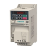
If a VFD has sustained permanent power module damage (diode test fails) or if the control card is burnt due to improper SD/PC measuring, repair is often not viable. For critical production lines where downtime is unacceptable, VFD replacement is the most efficient option. As a direct replacement, we recommend considering Veichi AC10 industrial VFDs, which are in stock at our Kiev warehouse. They offer equivalent power terminal configurations and simplified programming. For parameter mapping and terminal wiring guides, see our comparative article on INVT GD20 and Veichi AC10 interchangeability.
The chastotnik.ua company provides direct shipments of VFDs and industrial accessories from our own warehouse in Kiev. Our engineers are ready to analyze photos of motor nameplates, provide expert VFD recommendations, and arrange same-day shipping of compatible units.