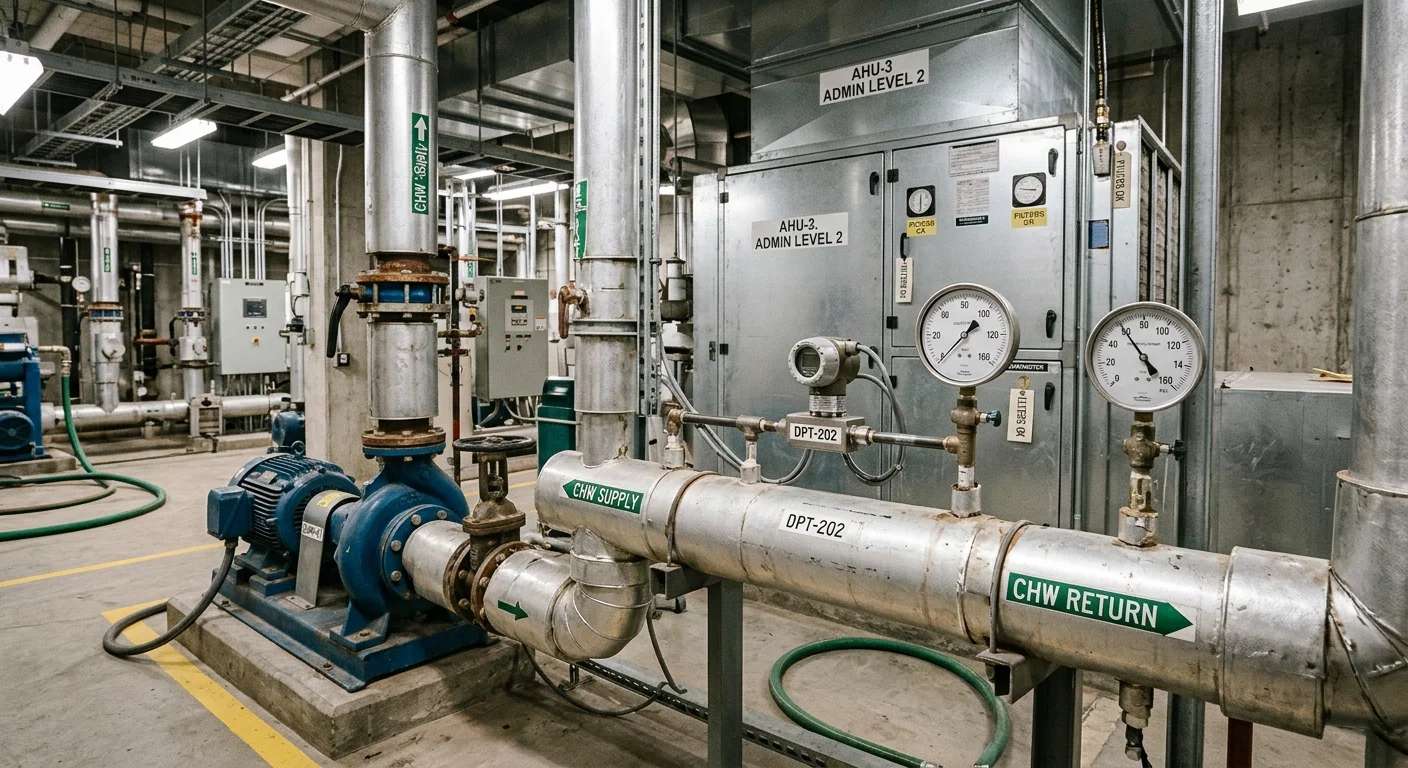
Three different instruments sold under one name
If the job comes down to an alarm or stopping a fan, a differential pressure switch is enough. If you need a filter loading trend or a flow calculation, you need a transmitter with an analogue output. If the value has to be read at the device, away from the panel, you need a version with the letter D and a built-in display. The specific models for each of the three cases are collected below, in the catalogue table.
A search for "differential pressure sensor" returns three different classes of instrument, and confusing them costs either money or a ruptured diaphragm. The difference is not quality or brand, it is what the device sends out.
Differential pressure transmitter
Measures the difference between two points and sends it out as a continuous analogue signal. The typical HVAC example is the Siemens QBM3020-5: range 0…500 Pa, output DC 0…10 V, supply AC 24 V ±15 % or DC 13.5…33 V. The controller sees an actual number rather than a clogged/not-clogged flag, so it can hold a setpoint, log a trend and raise its own alarm.
Differential pressure switch
Gives a dry contact: tripped or not. In the Dwyer DXW-11-153-2 this is an SPDT snap switch rated 5 A at 125/250 VAC and 5 A resistive at 30 VDC. No pressure value leaves the device, only the fact that the setpoint was crossed, and the setpoint itself is adjusted with an external screw.
Differential pressure gauge
An indicating instrument: a dial or display at the installation point, with no signal to the system required. In catalogue practice the word covers both purely mechanical dial gauges and electronic transmitters with a readout. The second group includes the QBM3020 versions carrying the letter D, for example the QBM3020-5D, which has both the 0…10 V output and a two-line LCD of eight positions per line showing differential pressure directly in pascals. In a modern price list, "gauge" usually means a transmitter that was given a screen.
The practical rule is short. If all you need is to stop a fan or raise an alarm, a switch is enough. If you need to watch a filter load up over time, or to derive flow, you need a transmitter with an analogue output.
Units: pascals, millibars, psi
Differential instruments live in two separate unit worlds, and that is the main source of selection errors. Ventilation counts in pascals, hydraulics in bar or psi. The Siemens datasheet prints the conversion as a single line: 100 Pa = 1 hPa = 1 mbar. On that basis the whole QBM3020 family fits between 0.5 mbar and 25 mbar:
- QBM3020-1U — minus 50 to plus 50 Pa, that is ±0.5 mbar, bidirectional;
- QBM3020-1 — 0…100 Pa, 0…1 mbar;
- QBM3020-3 — 0…300 Pa, 0…3 mbar;
- QBM3020-5 — 0…500 Pa, 0…5 mbar;
- QBM3020-10 — 0…1000 Pa, 0…10 mbar;
- QBM3020-25 — 0…2500 Pa, 0…25 mbar.
For comparison, the smallest Dwyer switch in the catalogue, the DXW-11-153-1, has a setpoint range of 2.5…10 psid, and the manufacturer prints the bar equivalent next to it: 0.17…0.69 bar. Its lowest setpoint of 0.17 bar is 17 000 Pa, roughly 170 times the full span of a QBM3020-1. These devices do not compete, they belong to different jobs.
Three jobs, three different demands on the instrument
Filter in an air handling unit
The classic job: show that the cartridge is due for replacement. The drop across a clean filter and a loaded one differs by a large factor, yet both values sit in the tens and hundreds of pascals. In its list of QBM3020 applications Siemens names filter monitoring and fan control explicitly, along with pressure supervision in laboratories, production areas and clean rooms. The range is picked from the final pressure drop: if the loaded cartridge ends up around 250 Pa, a QBM3020-5 (0…500 Pa) is the fit, not a QBM3020-25, on which that point lands in the first ten percent of the scale.
Fan and air flow
Flow does not follow differential pressure linearly, so the QBM3020 datasheet provides two characteristic curves selected by a DIP switch: pressure-linear (the factory setting) and extracting-the-root. On the square-root curve a potentiometer sets the end value, and the datasheet gives a different adjustment window per version: ±(30…50) Pa for -1U, 50…100 Pa for -1, 100…300 Pa for -3, 300…500 Pa for -5, 500…1000 Pa for -10 and 1600…2500 Pa for -25. Siemens also names VAV plants with variable air flow on the supply and extract side.
Pump, heat exchanger, liquid filter
Here the medium is a pressurised liquid, and the HVAC device is excluded by definition: the QBM3020 datasheet lists air and non-aggressive gases as the medium, and the pressure connection is a PVC nipple of 6.2 mm diameter for plastic tubing. For liquid you take a DX series switch: per its bulletin it serves compatible gases and liquids, the wetted parts are a brass connection and a fluoroelastomer diaphragm, and the process connection is 1/4" NPT female. The 200 psig pressure limit, that is 13.8 bar, lets it sit in a line that is itself pressurised and still resolve a drop of a few tenths of a bar across it. If the job is system pressure rather than differential pressure, that is a different class of instrument, covered separately in the article on pressure sensor types and ranges, and for pump sets in a dedicated selection guide.
Choosing a range without wrecking the instrument
Overload is rated per port, not per device
This is the least obvious item in the whole datasheet, and it is what kills sensors. Siemens rates tolerable one-sided overload with two different numbers: at port P1 it is 5000 Pa, and 10 000 Pa on the -5, -10 and -25 versions, while at port P2 it is only 400 Pa. The ports are asymmetric, and the gap between them is more than tenfold.
Work out what that means in spans. On a QBM3020-1 with a 0…100 Pa range, the 5000 Pa P1 limit is fifty full spans, while the 400 Pa P2 limit is four. On a QBM3020-5 with a 0…500 Pa range, P1 takes 10 000 Pa, that is twenty spans, while P2 still takes 400 Pa, less than a single span. Swap the tubes at commissioning, push a couple of kilopascals into P2 with the fan, and the device is gone. The datasheet continues: rupture pressure is 1.5 times the overload across 0…70 °C and 2 times the overload at room temperature.
The DX switch words its limit differently but means the same thing: continuous single-side-only pressure must not exceed 1.25 times the full differential range. "Full differential range" here means the top of the setpoint range, that is 25 psi for the -2 version. For the DXW-11-153-2 that works out at 1.25 × 25 = 31.25 psi, roughly 2.15 bar. Note how far that is below the 200 psig in the pressure-limits line: the device holds 13.8 bar when pressure is applied to both sides, while a one-sided head is capped around two bar. Open one valve before the other and you are outside the datasheet without ever approaching the 200 psig figure.
A switch always has deadband
A switch trips at one value and resets at another, and in the DX series that difference is tabulated. For the 2.5…10 psid range the deadband is 1.5 psi (0.10 bar) at the low setpoint and 2.5 psi (0.17 bar) at the high setpoint. For the 10…25 psid range it is 2.5 psi (0.17 bar) and 3.5 psi (0.24 bar) respectively. So at the bottom of the 10…25 psid scale you cannot get a response window tighter than 2.5 psi, a quarter of the setpoint itself. If the job needs a narrower window, a switch is the wrong device and the setpoint belongs in the controller.
Repeatability of the switch is stated separately as ±2 % of full range, which is not the same number as deadband. If you would rather not work it out yourself, send us the final differential across the loaded filter cartridge, the medium and the controller input type, and we will verify the version against the datasheet.
Mounting: orientation decides more than it looks
The QBM3020 datasheet carries a warning that is routinely ignored: the values given under technical data apply only to a vertically mounted sensor, meaning the pressure nipples point down. Mounted horizontally, with the cover up or down, deviations are possible, and the manufacturer offers the zero-point button to compensate them.
The second requirement concerns condensate. The sensor must sit not just nipples-down but also higher than the air duct probes. The datasheet states the consequence plainly: if the pressure connection nipples point upward or sit lower than the probes, condensation collects inside the sensor and damages the device. Two metres of plastic tubing is supplied and is trimmed on site to the real distance.
Tubing has one unambiguous rule: the higher-pressure side (lower vacuum) goes to nipple P1, also marked "+", and the lower-pressure side (higher vacuum) goes to P2, marked "−".
The DX switch has a different geometry. Mounting orientation is ports on the horizontal plane, ±10°. The high pressure port is marked "+" and is on the left side with the label side facing you, the low port "−" on the right. Piping must be supported on its own, not hang on the device, and when tightening the thread you hold a wrench on the flats of the pressure connection rather than feeding torque into the body. The system must be depressurised before the device is installed or removed.
Wiring
The QBM3020 has three terminals: G (+) for the AC 24 V or DC 13.5…33 V supply, M (0) for ground and measuring neutral, and U with an arrow for the DC 0…10 V signal. The connection is 3-wire, not galvanically separated, the output is short-circuit proof and protected against reverse polarity, and the load at the controller input must exceed 10 kΩ. Consumption is under 0.5 VA and under 10 mA, so one transformer feeds several sensors, but it must be SELV with separate windings and designed for continuous (100 %) duty. The 24 V power supplies in the catalogue cover this. The UL requirement adds a 15 W limit on the supply and copper wiring only. Supply line protection is a slow fuse up to 10 A, or a circuit breaker up to 13 A with characteristic B, C or D per EN 60898, or a source with current limitation up to 10 A. And a separate point for long runs: if the cable exceeds 50 metres and runs parallel to mains cables, it must be shielded. Terminals take wire up to 1.5 mm², the entry is Pg 11, the housing is IP54 per EN 60529 and protection class III per EN 60730-1. The catalogue holds the DC 0…10 V versions; if your controller input only takes 4…20 mA, write to us with the input model and we will verify the version against the datasheet.
The DX switch wires through a removable terminal block with three contacts: NC, NO and COM. The bulletin gives the logic directly: with differential pressure above the setpoint NO is closed and NC is open; below the setpoint the opposite. The bulletin recommends wire rated 250 V at 60 °C, 14 to 24 AWG (2.5 to 0.25 mm²), PVC or equivalent insulation, 94-V0 or FV-0 flammability rating. The conduit hole is 0.871 inch in diameter for a 1/2" fitting. The bulletin stresses separately that condensation must not be allowed to enter the sensor housing through the conduit, and that a conduit breather drain in a separate conduit body is installed where needed. If the contact lands on a discrete controller input, it is worth checking the input logic against the guide to wiring sensors to a PLC.
Zero, characteristic and setpoint
QBM3020 commissioning follows a datasheet order: first wire the connection terminals, with the pressure tubing still disconnected at this step; then press and hold the zero-point button for more than two seconds until the LED briefly lights and, on LCD versions, "0 Pa" appears; only then connect the pressure tubing. A press shorter than two seconds opens a menu on LCD versions, which closes by itself after eight seconds or through repeated presses of the button. The characteristic is switched with a DIP switch, factory set to pressure-linear.
The DX setpoint is adjusted with an external slotted screw under a rubber plug on the right side of the unit with the label side facing you. Clockwise increases the setpoint, counterclockwise decreases it. The bulletin sets a hard limit: do not turn the screw to the point where there are no longer any female threads visible in the switch body. Adjustment is made from a pressure source with a gauge while monitoring the contact output, not by eye. For the general procedure of setting a pressure switch, see the article on adjusting a pressure switch.
What is in the catalogue
| Model | Instrument class | Datasheet range | Output | Datasheet limit |
|---|---|---|---|---|
| Dwyer DXW-11-153-1 | differential pressure switch | 2.5…10 psid (0.17…0.69 bar) | SPDT, 5 A / 250 VAC | pressure 200 psig (13.8 bar); one-sided ≤ 1.25 × range |
| Dwyer DXW-11-153-2 | differential pressure switch | 10…25 psid (0.69…1.72 bar) | SPDT, 5 A / 250 VAC | pressure 200 psig (13.8 bar); one-sided ≤ 1.25 × range |
| Siemens QBM3020-1U | transmitter, bidirectional | −50…+50 Pa (±0.5 mbar) | DC 0…10 V | P1 5000 Pa / P2 400 Pa |
| Siemens QBM3020-1 | transmitter | 0…100 Pa (0…1 mbar) | DC 0…10 V | P1 5000 Pa / P2 400 Pa |
| Siemens QBM3020-5 | transmitter | 0…500 Pa (0…5 mbar) | DC 0…10 V | P1 10 000 Pa / P2 400 Pa |
| Siemens QBM3020-10 | transmitter | 0…1000 Pa (0…10 mbar) | DC 0…10 V | P1 10 000 Pa / P2 400 Pa |
| Siemens QBM3020-5D | transmitter with LCD | 0…500 Pa (0…5 mbar) | DC 0…10 V plus readout in Pa | P1 5000 Pa / P2 400 Pa |
The cards for these models sit in the sensor catalogue: Siemens items and Dwyer instruments items. For a wider choice, the all pressure sensors section holds both system-pressure and differential-pressure positions. If a version needs to be checked against its datasheet for your application, write to us with the model number and the site conditions.
Common mistakes
- Range taken oversized "just in case". A 0…2500 Pa device on a filter whose working point is 200 Pa runs in the first eight percent of the scale, where zero error and temperature drift eat the whole signal. Datasheet accuracy is specified as a percentage of full scale, not of reading.
- Tubing connected the wrong way round. On a QBM3020 that means feeding pressure into the port rated 400 Pa instead of the port rated 5000 or 10 000 Pa.
- An air sensor fitted to water. The QBM3020 datasheet limits the medium to air and non-aggressive gases, and the connection is a 6.2 mm PVC nipple for tubing. Steam, hot or aggressive media call for different wetted parts and often a syphon ahead of the instrument: pressure sensors for steam and aggressive media.
- Expecting a number from a switch. A dry contact does not report differential pressure. If a filter loading trend is needed, the switch is replaced by a transmitter, not "tuned more precisely".
- Deadband ignored. A switch set to 12 psi within the 10…25 psid range resets not at 12 but at roughly 9.5 psi.
- Housing fixed wherever it fitted. QBM3020 datasheet accuracy holds only for the vertical position with nipples down, and the sensor must sit above the duct probes.
FAQ
How does a differential pressure sensor differ from a differential pressure gauge?
A sensor, or transmitter, sends a signal to the system; a gauge shows the value locally. In modern catalogues the line is blurred because electronic versions do both: the QBM3020-5D has the 0…10 V output and a two-line LCD showing differential pressure in pascals. When a supplier calls something a gauge, the first question is whether it has an output signal.
Which range should I pick for a filter in an air handling unit?
Work from the final pressure drop across a loaded cartridge so that the working point lands in roughly the upper half of the scale. The QBM3020 family covers 0…100, 0…300, 0…500, 0…1000 and 0…2500 Pa, and the -1U version measures both ways, from minus 50 to plus 50 Pa. Take the smallest range that comfortably contains the working point.
Can a QBM3020 be used on a water filter?
No. The datasheet medium is air and non-aggressive gases, admissible medium temperature is 0…70 °C, and the connection is a plastic nipple of 6.2 mm for tubing. For liquid you need wetted parts rated for it, for example a DX series switch with a brass 1/4" NPT connection and a fluoroelastomer diaphragm.
What happens if P1 and P2 are swapped?
On a QBM3020 the P2 port tolerates only 400 Pa of one-sided overload against 5000 Pa at P1, or 10 000 Pa on the -5, -10 and -25 versions. What kills the device is not the swap itself but exceeding those 400 Pa at P2: as long as the working pressure at that nipple stays below the figure, the reading on the -1U and -1 simply changes sign and the cell survives. Feeding a working head above 400 Pa into the wrong nipple puts the device outside its datasheet immediately. Rupture pressure is given as 1.5 times the overload across 0…70 °C and 2 times the overload at room temperature.
The device does not read zero with the fan stopped. Is it faulty?
Usually not. QBM3020 datasheet values apply only to vertical mounting with the nipples down; in any other position the manufacturer explicitly expects deviations and offers the zero-point button to compensate. The procedure is to disconnect the tubing, hold the button for more than two seconds until the LED flashes or "0 Pa" appears on the display, then reconnect the tubing.
The switch trips but will not reset. Why?
Most likely the differential has not fallen below the reset point. In the DX series deadband is tabulated: for the 10…25 psid range it is 2.5 psi (0.17 bar) near the low setpoint and 3.5 psi (0.24 bar) near the high one. Until the differential drops that far below the setpoint, the contact stays in its tripped state.
Can a DX switch be used in a hazardous area?
The DX series bulletin this article is written from lists CE and UL approvals only, and describes the enclosure as weatherproof UL type 4X (IP65). There is no explosion-protection marking in that document, so a classified area needs a version with an explicit Ex certificate and its own datasheet.