Solar Panel Wiring Schemes: Series vs Parallel Connection
For grid-tied and hybrid residential solar installations rated between 3 kW and 15 kW, connecting solar panels in series strings—or combining identical strings into separate MPPT trackers—is the optimal engineering choice in over 90% of projects. Pure parallel wiring is primarily reserved for low-voltage 12 V or 24 V off-grid setups, such as RVs, marine systems, or small remote lighting backup stations.
The reasoning stems directly from Ohm's law: higher DC voltage means lower current, allowing smaller cable gauges and drastically cutting thermal resistance losses. However, miscalculating open-circuit voltage during sub-zero winter mornings can permanently destroy the input circuits of a hybrid inverter. Here is a technical breakdown of how each wiring method behaves, how to size strings accurately, and how to safeguard the array.
The Three Fundamental Solar Panel Wiring Methods
Every photovoltaic module lists its key ratings under Standard Test Conditions (STC: 1000 W/m² irradiance, +25°C cell temperature). System sizing relies on open-circuit voltage (Voc), maximum power voltage (Vmp), short-circuit current (Isc), and maximum power current (Imp). Interconnecting solar panels dictates total array voltage and operating current.
1. Series Connection (Stringing)
In a series string, the positive terminal of the first panel plugs into the negative terminal of the second, and so forth. The remaining negative lead from panel one and positive lead from the final panel form the DC string connected to the inverter.
- Voltage sums up: V_total = V1 + V2 + ... + Vn. A string of 10 modules with Vmp = 38 V operates at 380 V under standard conditions.
- Current remains constant: I_total = I1 = I2. String amperage equals that of a single module (typically 13.5 A).
- Key advantages: Modest amperage allows standard 4–6 mm² solar cables across runs of 30–50 meters without significant voltage drop. The inverter starts up earlier in the morning and sustains power longer into dusk.
- Main disadvantage: Bottleneck effect. Partial shading on even one module restricts the current of the entire string, despite built-in bypass diodes.
2. Parallel Connection
In a parallel circuit, all positive leads connect into a single junction via MC4 branch splitters, and all negative leads connect into another.
- Current sums up: I_total = I1 + I2 + ... + In. Four 13.5 A modules deliver 54 A into the shared trunk line.
- Voltage remains unchanged: V_total = V1 = V2 (typically 38–42 V).
- Key advantages: Complete electrical isolation between panels. Shading on one module has no bearing on neighbouring panels. Operating voltage remains under 60 V DC touch-safe limits.
- Main disadvantage: Carrying 50–70 A requires thick 16–25 mm² copper cables to curb resistive heat losses, driving up balance-of-system costs. Most grid-tied string inverters will fail to boot up at such low voltages.
3. Series-Parallel (Combined) Connection
This layout groups modules into multiple identical series strings, which are then wired in parallel. It scales both voltage and amperage proportionally to match large inverter ratings.
- Panels are divided into identical groups (for example, two strings of 8 modules).
- Each string is wired in series, producing 8 × 40 V = 320 V at 13.5 A.
- The two strings parallel into the inverter (via MC4 branch connectors or a DC combiner box with gPV fuses), delivering 320 V at 27 A (yielding roughly 8.6 kW peak).
Comparison of Solar Panel Wiring Methods
| Parameter | Series (String) | Parallel | Series-Parallel |
|---|---|---|---|
| Array Voltage | High (150–800 V) | Low (18–50 V) | Medium to High (300–600 V) |
| DC Cable Current | Low (10–15 A) | Very High (30–80 A) | Moderate (20–35 A) |
| Cable Cross-Section | 4–6 mm² | 10–25 mm² | 6–10 mm² |
| Shading Impact | Restricts the entire string | Isolated to shaded panel | Affects only the shaded string |
| Protection Hardware | 16 A DC breaker, Type II SPD | Individual branch fuses, 63 A breaker | gPV fuses per string + DC isolator breaker |
| Typical Applications | Grid-tied & hybrid rooftop solar | 12/24 V off-grid setups, RVs, boats | Commercial arrays, 6–30 kW residential systems |
Cold-Weather Voc Sizing: Why Voltage Climbs in Winter
A common engineering oversight is sizing module counts strictly against STC nameplate figures. Crystalline silicon has a negative temperature coefficient of open-circuit voltage (beta or Tk Voc, typically -0.26% to -0.30%/°C). When temperatures drop, open-circuit voltage rises substantially.
In Eastern European winter conditions, design minimums reach -25°C. Comparing this to STC (+25°C) yields a Delta T of 50°C:
Voc_max = Voc_stc × (1 + (|beta| / 100) × Delta T)
Taking a standard 540 W module (as reviewed in our guide on solar panel output 400 W vs 500 W vs 600 W):
- Nameplate Voc = 49.5 V.
- Temperature coefficient beta = -0.28%/°C.
- Cold voltage gain: 50 × 0.28% = +14%.
- Peak winter Voc: 49.5 × 1.14 = 56.43 V per panel.
If an inverter caps out at 500 V DC max input, an untrained installer might place 10 modules in series (10 × 49.5 V = 495 V < 500 V). On a frigid -25°C dawn, that string will hit 564.3 V open-circuit, tripping over-voltage faults or blowing input varistors.
Matching String Parameters to Inverter MPPT Windows
To maximize annual energy yield, keep array voltage squarely within the MPPT tracking window under all operating conditions:
- Start-up Voltage: Typically 120–150 V for single-phase units and 180–200 V for three-phase inverters. Summer operating voltage (Vmp at cell temperatures up to +65°C, where panels lose 10–12% voltage) must sit comfortably above this threshold by at least 25–30 V.
- MPPT Voltage Window: A Deye 6 kW inverter features a 150–425 V MPPT window. Operating below 150 V prevents full-rated output. Targeting 320–380 V provides optimal conversion efficiency. For complete system integration, review our guide on connecting a hybrid inverter to solar panels.
- Maximum MPPT Input Current: High-power bifacial modules generate 13–15 A Imp, surging up to 17 A with albedo reflection. Ensure the inverter input amperage handles this headroom without clipping.
Battery Bank Wiring Schemes
Battery bank topologies must match the inverter DC bus specification:
- Low-Voltage 48 V Architecture: The dominant residential standard up to 8 kW. Modern 48 V / 51.2 V LiFePO4 batteries (100 Ah to 280 Ah modules) connect in parallel across heavy-duty copper busbars. Amp-hour capacity increases while nominal voltage holds at 48 V. Learn more in our guide on solar battery selection or browse our LiFePO4 battery modules.
- High-Voltage 160–800 V Architecture: Standard for commercial three-phase installations above 10 kW. Modular battery packs stack in series under a master high-voltage BMS controller to sum voltages to 300–600 V DC.
DC Protection and Safety Hardware
Unlike AC, DC arcs do not cross a zero-voltage threshold and are notoriously difficult to extinguish. Every array installation demands dedicated DC switchgear:
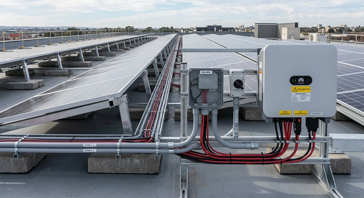
- 2-Pole DC Circuit Breaker: Rated specifically for 600 V or 1000 V DC. Standard AC breakers must never be installed on solar arrays, as they cannot quench DC arcs and pose a severe fire hazard.
- gPV String Fuses: Required when paralleling three or more strings. If a short circuit develops in one branch, backfeed from adjacent strings is cleared by the 15–20 A gPV fuse.
- DC Surge Protection Device (Type II SPD): Protects inverter electronics from induced lightning transients.
- System Grounding: Racking rails and panel frames must be bonded with 6 mm² copper conductor to a dedicated earth ground achieving <4 Ohms resistance.
Frequently Asked Questions
Is series or parallel better for connecting solar panels?
For modern grid-tied and hybrid inverters, series stringing is standard because it achieves the 150–400 V MPPT operating window while keeping cable current low. Parallel connections are suitable only for small 12/24 V battery systems with PWM controllers or when paralleling two matching strings into one inverter input.
What happens when one panel in a series string is shaded?
The entire string current drops to match the bottleneck of the shaded cells. Bypass diodes partially mitigate output losses by routing current around shaded cell groups, but the string still loses 30% to 80% of its potential yield. Tigo power optimizers or microinverters are recommended for complex roof shade.
Can you mix solar panels of different wattages?
Mixing wattages in series is strongly discouraged because the total string current is constrained by the lowest-amperage module. Paralleling mismatched strings requires identical operating voltages (Vmp); otherwise, parasitic circulating currents will cause permanent energy loss.
How many solar panels can be wired into a single string?
Divide the inverter maximum DC input voltage by the cold-weather Voc (-25°C rating) of the chosen module. For a 500 V inverter limit and a cold Voc of 56.4 V: 500 / 56.4 = 8.8, meaning 8 modules is the absolute maximum safe string size.
Do I need fuses for two parallel strings?
Two parallel strings rarely require fuses because backfeed current from one string cannot exceed the maximum reverse current rating (I_reverse, typically 20–25 A) of the other. However, once three or more strings are paralleled, IEC 62548 mandates gPV fuses on both positive and negative lines.
Conclusion and Equipment Selection
Designing a dependable solar array hinges on three engineering rules: delivering sufficient voltage to maintain efficient MPPT tracking, preserving a safe margin below maximum cold-weather Voc, and minimizing line currents. For most homes, one or two balanced strings of 7 to 10 panels strike the ideal balance.
If you are planning an installation or array expansion, our technical specialists can verify string configurations against your inverter specifications. Explore our catalog of Tier-1 solar panels or contact our engineering desk for tailored assistance with DC balance-of-system hardware.