Why power supply redundancy matters
Most industrial power supplies are rated with a mean time between failures (MTBF) of 200,000 to 500,000 hours. That sounds impressive, but MTBF is a statistical property of a production batch, not a guarantee for any individual unit. Real-world failure causes include: ventilation slot blockage leading to overheating, mains voltage transients, and electrolytic capacitor ageing after 5-7 years of operation.
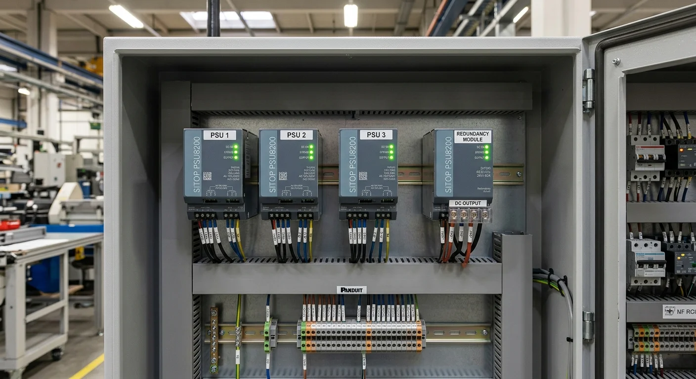
For continuous lines in food production, access control systems, or telecom racks, a power supply failure costs more in downtime than a second unit. N+1 is the minimum sufficient redundancy: two units share the load in normal operation, or one standby unit waits in hot-standby mode.
Why outputs cannot simply be wired in parallel
The intuitive approach is to connect two power supplies in parallel to double the available current. The problem is that power supplies without a dedicated load-sharing circuit have different actual output voltages within the manufacturer's tolerance band (for example, 24.1 V and 23.9 V).
The unit with the higher voltage absorbs all the load current while the second unit runs almost unloaded. The first unit may overheat and fail. On failure, the voltage drops sharply to the level of the second unit. There is also a reverse current risk: the unit with the lower voltage becomes a load for the other one.
Conclusion: parallel output connection without isolation is not safe.
Schottky diode ORing
The classical solution: install an isolation diode between the output of each power supply and the common load bus. The unit with the higher output voltage naturally carries more of the load; the second unit stays in hot standby. If the first unit fails and its voltage drops, the second unit's diode conducts and takes the full load.
Schottky diodes are preferred here because of their lower forward voltage drop (0.3-0.5 V versus 0.7 V for silicon diodes), which reduces heat dissipation and power loss. For currents of 10-20 A, TO-220 or TO-247 packages with a heatsink are appropriate.
An important detail: the diode forward voltage drop reduces the voltage reaching the load. If the load requires exactly 24 V, set each supply's output to 24.4-24.5 V using the Vadj trim resistor.
Ideal diode circuits — the modern alternative
Ideal diode controller ICs drive a MOSFET to emulate a diode with a near-zero voltage drop (less than 50-100 mV). This eliminates the voltage loss and heat generation associated with passive Schottky diodes.
Common ICs: LTC4412, LT4352, MAX40200. An ideal diode circuit is a separate external component; it is not integrated into the power supplies in our catalogue. It is mounted on a separate PCB or sourced as a ready-made ORing module from third-party suppliers.
Voltage balancing with Vadj
Most industrial power supplies include a Vadj trim resistor or potentiometer that allows the output voltage to be adjusted within ±5-10% of nominal. When using two supplies in an N+1 scheme, set both to the same voltage — within 0.05 V of each other. If there is a voltage mismatch, the higher-voltage unit carries all the load.
For a Schottky diode scheme, compensate for the diode drop: if you are using two NDR-120-24 units (24 V nominal, ~0.4 V drop across the diode), set both to 24.4 V. After assembly, verify the bus voltage under load with a voltmeter and adjust if needed.
DC-OK signal and monitoring
Most industrial power supplies have a DC-OK (or Power Good) signal output — a relay or open-collector output that closes during normal operation and opens on failure. Connect the DC-OK outputs of both supplies to a PLC or alarm controller.
Without monitoring, an N+1 scheme works silently: the first unit fails, the second takes the load, and the system continues running — but there is no longer any redundancy. The operator only discovers the failure when the second unit fails too. DC-OK provides timely notification and allows the failed unit to be replaced before a critical situation develops.
Example supply pairs for N+1
| Model (×2) | Voltage | Current per unit | Power per unit | Form factor |
|---|---|---|---|---|
| NDR-120-24 | 24 V | 5 A | 120 W | DIN rail |
| LRS-150-24 | 24 V | 6.5 A | 150 W | Enclosed |
| NDR-240-24 | 24 V | 10 A | 240 W | DIN rail |
For N+1, use two identical units — this simplifies Vadj balancing and ensures symmetric loading. Browse the full range on the industrial power supplies or DIN rail power supplies pages.
For guidance on power sizing and voltage selection, see How to choose a power supply for a control cabinet and Which voltage to choose for a power supply.
If your requirement is unusual — send us your load list and we will size the solution within one working day.