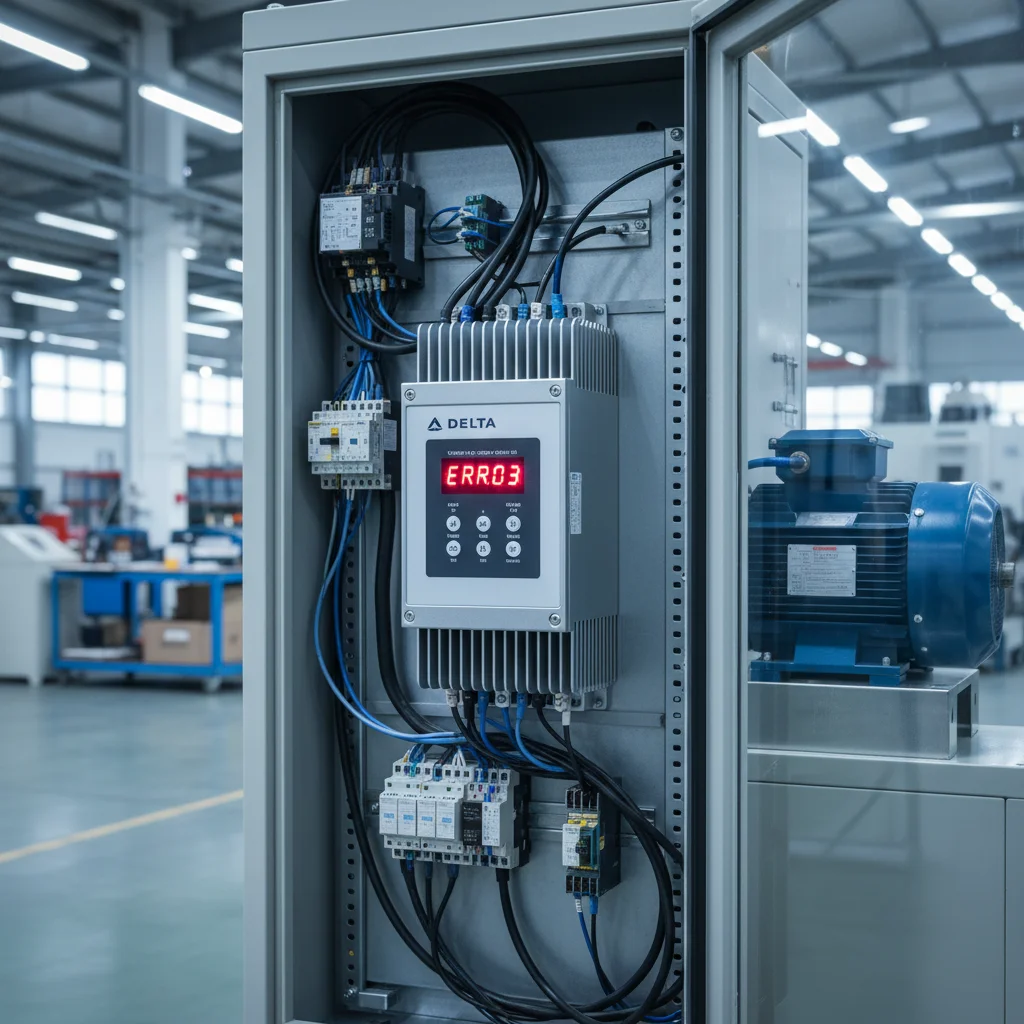
Delta VFD Error Codes: Fast Troubleshooting for oc, ov, uF, and oL
To eliminate emergency shutdowns of Delta Electronics variable frequency drives in MS300 and VFD-EL series, it is sufficient to know the exact troubleshooting steps for the four main fault codes: oc (overcurrent), ov (overvoltage), uF / Lv (undervoltage), and oL (overload). Our practice shows that more than 85% of fault trips are caused by external grid factors or incorrect settings of acceleration and deceleration dynamics. Only in rare cases do these faults indicate physical damage to the output IGBT power stage. Understanding the physics of these processes allows you to quickly return your equipment to service.
Step-by-Step Analysis and Resolution of Main Delta Fault Codes
Each individual protection code in Delta frequency converters has a clearly defined cause. A fault can occur during motor startup or during continuous operation under heavy loads. We recommend performing the diagnostic checks sequentially.
Fault oc (Overcurrent Protection)
An oc fault indicates that the output current has instantly exceeded the safe limit. The drive immediately shuts down its outputs to protect the transistors from damage. The root cause is typically a short circuit between motor phases or a ground fault.
We advise the following diagnostic procedure to resolve this fault:
- Disconnect the motor from terminals U, V, and W. Run the drive without any load at a low frequency of 10 Hz. If the oc fault still occurs, the power board or the IGBT module is shorted. A professional repair is required.
- Check the insulation resistance of the motor and cable. Be sure to measure the winding insulation resistance to ground using a megohmmeter. The normal resistance must be above 10 MOhms.
- Increase the acceleration time. Starting high-inertia mechanisms too fast requires excessive currents. Configure parameter 01-12 (MS300) or Pr. 01.12 (VFD-EL) to a higher value, such as 15 seconds instead of the factory default of 5 seconds.
- Reduce the torque boost level. The torque compensation parameter 07-02 (MS300) or Pr. 07.02 (VFD-EL) may be configured too high, causing current spikes during motor startup.
Fault ov (Overvoltage Protection on DC Bus)
The ov alarm occurs when the DC bus voltage in the main capacitor bank exceeds the critical safety threshold. This limit is set to 400 VDC for single-phase 220V models and 800 VDC for three-phase 380V models. This fault is most common during deceleration.
During deceleration, the motor begins to act as a generator, pumping kinetic energy back into the drive. To resolve this problem, perform the following actions:
- Increase the deceleration time. Adjust parameter 01-13 (MS300) or Pr. 01.13 (VFD-EL) so the motor stops more gradually. This drastically reduces the regeneration of energy.
- Enable the overvoltage stall prevention function. Set parameter 06-01 (MS300) to 1. This configuration allows the drive to automatically extend the deceleration time when the DC bus voltage approaches the danger limit.
- Install a dynamic braking resistor. This is the only reliable way to achieve fast stopping of high-inertia loads. The resistor absorbs and dissipates the regenerative energy as heat.
Fault uF (VFD-EL) or Lv (MS300) — Undervoltage Fault
The uF and Lv faults signal that the voltage across the DC bus capacitors has dropped below the minimum permissible level. For single-phase models, this threshold is 180 VDC, and for three-phase models, it is approximately 360 VDC. This is often caused by utility grid drops.
To resolve the undervoltage fault, perform the following checks:
- Verify the incoming AC voltage under load. If the line voltage drops significantly when other high-power machinery starts up, the VFD will trip immediately.
- Verify the tight connection of power terminals. Poor contacts on input terminals R, S, and T cause a local voltage drop. Tighten all terminals with the correct torque.
- Monitor the charging bypass relay. If the supply voltage is normal but the fault trips as soon as the motor starts, the internal bypass relay or charging resistor inside the Delta drive may be damaged.
Fault oL (Overload Protection)
An oL fault indicates that the system has operated under a continuous overload. The frequency converter distinguishes between drive overload (code oL1) and motor overload (code oL2). This protection is cumulative and depends on time.
You can eliminate overloads using the following steps:
- Check the mechanical part of the machine. Ensure the motor shaft can rotate freely without binding. A mechanical jam or a clogged impeller in pump applications will overload the system.
- Enter the exact motor rated current. Configure the rated motor current in parameter 05-01 (MS300) or Pr. 07.00 (VFD-EL). This allows the drive thermal model to protect the motor accurately.
- Upgrade the power rating of the VFD. If your current drive runs at its physical limits, replace it with a higher-rated unit. For example, instead of VFD015EL43A (1.5 kW), install VFD22AMS43AFSAA (2.2 kW).
Power Stage Diagnostics: Testing IGBT and Input Rectifier
If the Delta drive consistently trips with an oc fault even with the motor cables disconnected, you must perform a preliminary check of the power semiconductors. To do this, you will need a standard digital multimeter with a diode test function. Make sure all AC power is isolated, and wait at least 10 minutes for the internal capacitor bank to discharge fully.
Attention, important technical note: in several unofficial guides, the negative DC bus terminal (-) is mistakenly referred to as DCM. This is a severe technical error. The DCM terminal (Digital Common) is the control signal ground for logical inputs and has no connection to the high-voltage power circuitry. The negative DC bus terminal on Delta drives is labeled exclusively as (-) or (N). Attempting to use the DCM terminal for power stage diagnostics will yield invalid measurements and can confuse the technician.
To test the power modules, perform the following measurements using your multimeter in diode test mode:
| Circuit Under Test | Red Probe (+) | Black Probe (-) | Expected Reading |
|---|---|---|---|
| Input Rectifier (Upper half) | Terminals R, S, T | DC Bus (+) or +1/+2 | Diode drop within 0.3V to 0.7V |
| Input Rectifier (Lower half) | DC Bus (-) | Terminals R, S, T | Diode drop within 0.3V to 0.7V |
| IGBT Inverter (Upper half) | Terminals U, V, W | DC Bus (+) or +1/+2 | Diode drop within 0.3V to 0.7V (across freewheeling diodes) |
| IGBT Inverter (Lower half) | DC Bus (-) | Terminals U, V, W | Diode drop within 0.3V to 0.7V |
Any deviation from these ranges indicates a failed component. A reading of 0.00 V represents a short circuit, while an OL reading in both directions indicates an open diode or IGBT. In both cases, the drive requires hardware repair.
Using Braking Resistors to Solve ov Deceleration Faults
Installing an external braking resistor is the only effective solution to prevent ov faults during fast stops of high-inertia systems. Our engineering team regularly installs these components for industrial fans, centrifuges, and woodworking machines.
Delta MS300 drives have a built-in brake chopper (transistor) across all standard power ranges. The braking resistor is wired directly to terminals +2/B1 and BR. For VFD-EL drives, the resistor is connected to terminals (+) and (PB). Remember to disable the automatic overvoltage stall prevention parameter (set 06-01 to 0 in MS300), otherwise the drive will artificially extend the deceleration ramp, ignoring the presence of the resistor.
When selecting a braking resistor for Delta equipment, follow these specifications:
- Specification for 220V drive (0.75 kW): The nominal resistance must be at least 200 Ohms, with a power rating of at least 80 Watts. Aluminum housed resistors are highly recommended.
- Specification for 380V drive (1.5 kW): The minimum resistance is 400 Ohms, and the recommended power rating is 150 Watts.
- Specification for 380V drive (5.5 kW): The minimum resistance is 100 Ohms, with a power rating of at least 400 Watts. For heavy duty cycles, double the wattage.
Note: The resistance of the connected resistor must never be lower than the minimum value specified in the Delta Electronics user manual. Using a resistor with too low resistance will destroy the drive internal brake chopper.
Frequently Asked Questions about Delta VFD Faults
Why does the oc fault trigger instantly without any motor cable connected?
This is a clear indicator of an internal short circuit in the IGBT power module of the drive. The internal current sensors detect an overcurrent condition within the VFD itself. The Delta drive must be sent to a professional service center for power module replacement.
How can I protect the braking resistor from thermal runaway and fire?
We recommend installing a thermal overload switch or relay in series with the braking resistor. Wire the normally closed (NC) contacts of this thermal protection into the drive external fault input (e.g., EF terminal) or the control circuit of the main input contactor. This isolates the power immediately upon overheating.
Can I disable the oL protection in parameters to stop the drive from tripping?
While you can adjust thermal curves or overload protection settings in parameter group 06, disabling oL is extremely dangerous. Doing so will inevitably cause the motor winding insulation to overheat and burn out within a few minutes of operating under overload.
What is the difference between uF on VFD-EL and Lv on MS300?
Both codes represent the exact same physical failure: a drop in DC bus voltage below the safe minimum. The only difference is the symbol display format used on the keypads of different product generations. The diagnostics and causes for both codes are identical.
Does the grounding of a Delta drive affect the frequency of oc faults?
Yes. Without proper PE grounding, high-frequency leakage currents through the cable capacitance can interfere with the internal current sensors. This leads to nuisance oc trips. Always connect the drive grounding terminal to the main PE ground loop.
Summary and Professional Selection of Delta Equipment
Accurate diagnostics of Delta Electronics fault codes guarantees a long and reliable operation of your industrial assets. Fault codes oc, ov, uF, and oL are built-in protection tools that prevent expensive hardware damage when properly configured. If you are looking for a reliable industrial drive, consider the high-performance Delta MS300 series and the budget-friendly Delta VFD-EL series.
Our technical team is always ready to assist you with parameter configuration and dynamic braking accessories. We keep a large inventory of compatible braking resistors of various ratings and other automation products in stock. Contact our support today for expert advice.