Replacing Delta VFD-EL with Veichi AC10: Step-by-Step Engineering Retrofit Guide
During the modernization of industrial assembly lines or when repairing equipment, it is frequently necessary to replace a classic yet obsolete Delta VFD-EL frequency inverter with a modern, cost-effective alternative. Based on our practical field experience, the Veichi AC10 variable frequency drive is the optimal choice in this power class. Both drives target simple applications such as fans, pumps, and light conveyors, but Veichi offers a more advanced hardware platform and enhanced electronic thermal protection. However, a direct wire-to-wire replacement is impossible due to hardware differences in control terminal counts and NPN/PNP digital input configurations. Below is a practical guide to help you successfully transfer power circuits, control loops, and configuration parameters without external integration costs.
Power Terminals: Voltage Verifications and Braking Circuit Setup
To successfully migrate the high-voltage power stage, map connections strictly by their electrical function rather than relying on exact case-sensitive cabinet lettering. While input mains and motor lines are similar, dynamic braking configurations differ significantly.
When wiring the power terminals, follow these specific directives:
- AC Input Power Line: Delta VFD-EL drives designate input terminals as R/L1, S/L2, and T/L3. Veichi AC10 units label input terminals as R/L, S, and T/N. For single-phase 220V VFD configurations, wire active and neutral lines directly to R/L and T/N, leaving terminal S vacant.
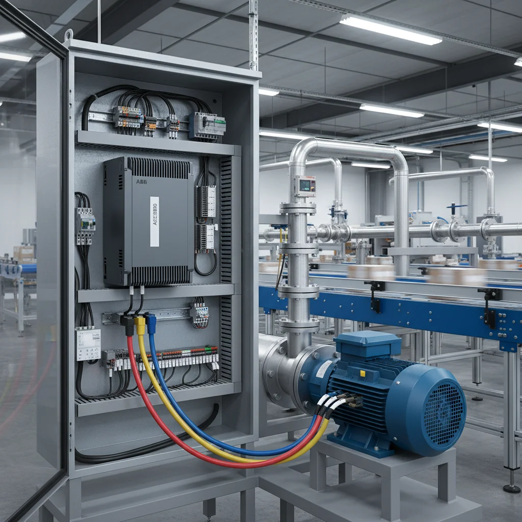
- Motor Output Interface: Connect the three motor stator lines to U/T1, V/T2, and W/T3 on the Delta drive, and map them to U, V, and W on the new Veichi AC10 inverter. Always connect the PE chassis grounding shields, maintaining ground loop resistance below 10 Ohms to mitigate high-frequency parasitic noise.
- Braking Resistor Connections: This is the main hardware divergence. Delta VFD-EL drives lack an integrated braking transistor (chopper) for most variants, necessitating an external brake unit (BUE) wired to the + and - terminals. Conversely, the Veichi AC10 has a built-in brake chopper. You can wire the dynamic braking resistor directly to the + and PB terminals, saving DIN-rail space and reducing integration costs.
⚠️ CRITICAL SAFETY LIMITATION: Before commencing cabinet work, inspect the input rating on the nameplate of the old Delta VFD. The VFD-EL series includes 115V input models. The Veichi AC10 line does not offer 115V models — its minimum input voltage rating is 220V. If the existing drive runs on a 115V supply, a direct swap is impossible without installing a step-up transformer or choosing an alternative VFD series.
Control Terminals: Digital Input Count Traps and NPN/PNP Logic Selection
Most field failures during retrofits occur due to incorrect wire transfers of control signals. The core challenge is that the Delta VFD-EL features 6 digital inputs (MI1 to MI6), whereas the Veichi AC10 offers only 4 digital inputs (X1 to X4/PUL) in its standard configuration.
To correctly map control loops, follow these engineering steps:
- Assess Digital Input Utilization: If the legacy Delta drive uses only MI1 (Forward Run) and MI2 (Reverse Run), you can easily map them to X1 and X2 on the AC10. If the Delta installation uses all 6 inputs (e.g., for multi-speed presets or external interlocks), you must simplify the control logic. Engineering solutions include combining speed preset steps, using serial RS-485 Modbus commands for drive control, or migrating to the high-end Veichi AC310 series which offers an expanded terminal block with more digital inputs.
- Verify Logic Selection (NPN vs. PNP): The Delta VFD-EL is typically configured for active-high PNP logic (Source), where terminals are triggered by a +24V signal. Small Veichi AC10 drives (up to 5.5 kW) are fixed for active-low NPN logic (Sink), meaning inputs trigger when shorted to GND (0V). If your PLC or control circuit outputs a +24V signal, you must either purchase the special `AC10-P` PNP model, or install interface relays to invert the logic signals. Veichi AC10 models 7.5 kW and above feature an integrated logic selection switch.
- Wire Analog Inputs for Speed Reference and Feedback Sensors: For external speed potentiometers, wire the three terminals to +10V (reference), AI (0-10V analog input), and GND (analog common). If wiring a 2-wire 4-20mA pressure transmitter for PUMP constant-pressure control, connect the sensor power to +24V and the return loop signal to terminal AI, switching the AI hardware DIP switch on the AC10 control board to Current mode ("I").
Parameter Mapping Table for Quick Commissioning
To accelerate commissioning, refer to this parameter mapping table. Do not copy motor nameplate values blindly: the Veichi AC10 requires rated motor power in kW, which was not explicitly defined in the legacy Delta parameter structure.
| Function | Delta VFD-EL Parameter | Veichi AC10 Parameter | Engineering Configuration Notes |
|---|---|---|---|
| Factory Reset | Pr. 00.02 = 9 (50Hz defaults) | F00.03 = 22 | After initializing the AC10, all motor parameters must be manually entered from the motor nameplate. |
| Motor Control Method | Pr. 00.10 (V/F or Vector) | F01.00 | Set to 0 for standard V/F control or 1 for sensorless vector control (SVC) under high-starting-torque loads. |
| RUN Command Source | Pr. 02.01 | F01.01 | Set to 1 to enable drive starting and stopping through external terminals X1/X2. |
| Frequency Reference Source | Pr. 02.00 | F01.02 | Select 1 or 2 for analog input AI, or select the integrated keypad potentiometer. |
| Maximum Output Frequency | Pr. 01.00 | F01.10 | Limit to 50.0 Hz to protect standard mechanical gearboxes and pump impellers from overspeed damage. |
| Acceleration / Deceleration Time | Pr. 01.09 / Pr. 01.10 | F01.22 / F01.23 | Set to a baseline of 5.0 to 10.0 seconds to prevent overcurrent trips during startup under inertia. |
| Motor Rated Current | Pr. 07.00 | F02.06 | Enter the exact motor rated Amps from the nameplate to calibrate the electronic overload relay. |
| Motor Parameter Auto-Tuning | Pr. 07.04 | F02.07 | Set to 2 (static tuning) or 1 (rotational tuning) and press RUN on the keypad. |
Step-by-Step VFD Replacement Procedure
For safe cabinet retrofits, execute the migration sequence in this exact order to prevent hardware damage and wiring errors:
- Record Existing Configurations: Before removing the old Delta drive, scroll through the parameter list and record the values in groups 00, 01, 02, 07, and 10. Pay special attention to PID targets and scaling values if the drive operates a constant-pressure water supply.
- Isolate Power: Turn off the main circuit breaker. Wait at least 10 minutes for the internal capacitor bank to discharge completely. Verify the absence of high voltage at the input and DC bus terminals with a multimeter before touching terminals.
- Label and Disconnect Wires: Photograph the existing connections. Label every wire according to its terminal designation (e.g., "MI1 Forward", "Potentiometer Slider", "+24V"). Carefully disconnect the control and power cables.
- Mount the New Veichi AC10: Mount the new drive on the DIN rail or backplate. Ensure at least 10 cm of clear space above and below the heatsink for unrestricted convective cooling.
- Communicate Wiring: Connect the AC mains supply to R/L and T/N, and map the motor output to U, V, and W. Transfer the control wires using the terminal mapping table (e.g., connect the wire from MI1 to X1). Verify the NPN/PNP logic switch position and the analog input DIP switch.
- Program Inverter Parameters: Apply power to the drive. Navigate to group F02 and enter the nominal motor nameplate ratings. Perform a static auto-tune via parameter F02.07. After successful completion, set F01.01 = 1 (terminal start) and configure the frequency reference source F01.02.
- Execute Test Run: Initiate a run command at a low frequency (5-10 Hz). Check the motor rotation direction. If reversed, swap two output phase wires on terminals U and V, or modify the parameter rotation setting. Test the analog speed pot and discrete switches across the entire operating range.
Frequently Asked Questions
What should I do if the Delta VFD-EL uses all 6 digital inputs MI, but the Veichi AC10 has only 4?
In this scenario, a direct one-to-one wire transfer is impossible. The best engineering approach is to migrate control to RS-485 Modbus RTU communications via the A+ and B- terminals, removing physical wires entirely. Alternatively, you can swap the drive for the premium Veichi AC310 series, which features a wider terminal block with 6 digital inputs.
How do I migrate the PID controller settings for pump applications?
To enable the PID controller on the Veichi AC10, set the frequency source parameter F01.02 = 8 (PID enabled). Map the analog feedback source in F13.01 (typically set to AI2) and program the target pressure setpoint in F13.07 (expressed as a percentage of the sensor span). Proportional gain Kp and integral time Ti are tuned in parameters F13.11 and F13.12.
Why does the Veichi AC10 fail to start after I wired the digital run switch?
This is typically caused by a logic mismatch. Most European-style cabinets use active-high +24V PNP signals. Because small Veichi AC10 drives are configured for active-low NPN logic (where inputs trigger when connected to GND), you must install an interface relay to invert the signal or use the special PNP-compliant `AC10-P` drive model.
Can I run a single-phase 220V motor with a starting capacitor on the Veichi AC10?
We do not recommend connecting single-phase capacitor-start motors directly to a three-phase VFD output due to high risk of winding failure and overcurrent trips. The best practice is to remove the capacitor, wire the main winding to U-V and the auxiliary winding to U-W, and disable the output phase loss protection by setting parameter F11.07 = 0.
How do I enable auto-restart after a brief power failure?
To allow the drive to automatically resume operation after a power sag, configure the auto-restart parameters. Set F07.06 = 1 (enable auto-restart after power loss) and program the restart delay in F07.07 (e.g., 2.0 seconds to allow water hammer or mechanical inertia to settle before restarting).
Conclusions and Engineering Recommendations
Modernizing industrial systems by replacing a Delta VFD-EL with a Veichi AC10 substantially increases drive performance and motor thermal protection at a highly competitive cost. Success depends on verifying the number of active digital inputs, supply voltage, and NPN/PNP logic types before wiring. Following our structured parameter transfer table and executing terminal routing by function ensures an error-free swap. Our company keeps a vast stock of industrial drives in Kiev, allowing for same-day dispatch. Browse our catalog for competitive Veichi frequency converters, explore our comparative guide on INVT GD20 and Veichi AC10 interchangeability, and view our general listing of frequency inverters directly from our warehouse.