Why stepper motors and CNC systems need a different approach to power supply selection
A standard industrial power supply is designed for stable resistive or lightly inductive loads. Stepper motors and servo drives behave differently: they draw pulse current during acceleration, and during braking they act as generators — returning energy back to the DC bus. This phenomenon is called regeneration, and it causes a brief voltage overshoot at the power supply output.
If the power supply is not rated for that overshoot, the overvoltage protection (OVP) trips, and the CNC controller stops mid-cycle. That is why selecting a power supply for a CNC machine or stepper-driven robot requires considering several factors that are typically absent from load specifications.
24 V or 48 V: which voltage to choose
Most modern stepper motor drivers and servo amplifiers accept supply voltages from 20 V to 80 V DC. The chosen voltage level directly affects the drive's dynamic performance.
Higher supply voltage increases the rate of current rise in the motor winding, which means more torque at high speeds and faster positioning. For CNC machines with demanding feed rate and accuracy requirements, 48 V is the right choice. For slow conveyor feeders or dosing systems with modest feed rates, 24 V is sufficient.
Servo drives typically have their own internal regulator and can operate from either 24 V (low power) or 48 V (medium power). Always verify the accepted voltage range in your specific servo amplifier datasheet.
Current headroom: why "just enough" is never enough
Peak currents during stepper or servo startup can be 3 to 5 times the rated holding current. If the rated load current equals the power supply's maximum output current, every startup event causes a voltage dip, and the driver may generate a fault or lose steps.
The practical rule: select a power supply with 30-50% headroom above the calculated peak current. For a machine with four stepper motors at 4 A each (16 A combined), the minimum supply rating should be 20 A.
Regeneration and protection against voltage spikes
When a motor brakes, the energy stored in the winding inductance returns to the DC bus. The power supply output voltage briefly rises above nominal. In some systems, this rise can reach 10-20% above the rated voltage.
There are several ways to protect against this:
- Buffer capacitor — an additional electrolytic capacitor on the DC bus (for example, 4700-10000 µF rated at 63 V for a 48 V system) absorbs the energy peak and holds the voltage within acceptable limits.
- Brake resistor — a resistor connected in parallel with the bus through a transistor switch. When voltage exceeds the threshold, the resistor connects and dissipates the excess energy as heat. Some drivers include a built-in switch for an external brake resistor.
- Wide OVP threshold — some power supplies have a higher OVP trip threshold (for example, 130% of nominal instead of 110%). This configuration is more tolerant of regenerative spikes.
Before selecting a power supply, confirm with the driver manufacturer what buffer capacitance is recommended and whether an external brake resistor is required.
Suitable power supply models for 24 V and 48 V systems
| Model | Voltage | Current | Power | Form factor | PFC |
|---|---|---|---|---|---|
| LRS-350-24 | 24 V | 14.6 A | 350 W | Enclosed | No |
| PMT-24V350W2BR | 24 V | 14.58 A | 350 W | Enclosed | No |
| NDR-480-24 | 24 V | 20 A | 480 W | DIN rail | Yes |
| DRM-24V480W1PN | 24 V | 20 A | 480 W | DIN rail | Yes |
| LRS-350-48 | 48 V | 7.3 A | 350 W | Enclosed | No |
| NDR-480-48 | 48 V | 10 A | 480 W | DIN rail | Yes |
| NDR-240-48 | 48 V | 5 A | 240 W | DIN rail | Yes |
The Mean Well NDR series and the Delta DRM/DRP series feature active PFC, which reduces the reactive current component drawn from the mains — relevant for cabinets with multiple drives. The LRS and PMT series without PFC are less expensive but introduce more harmonics into the supply network.
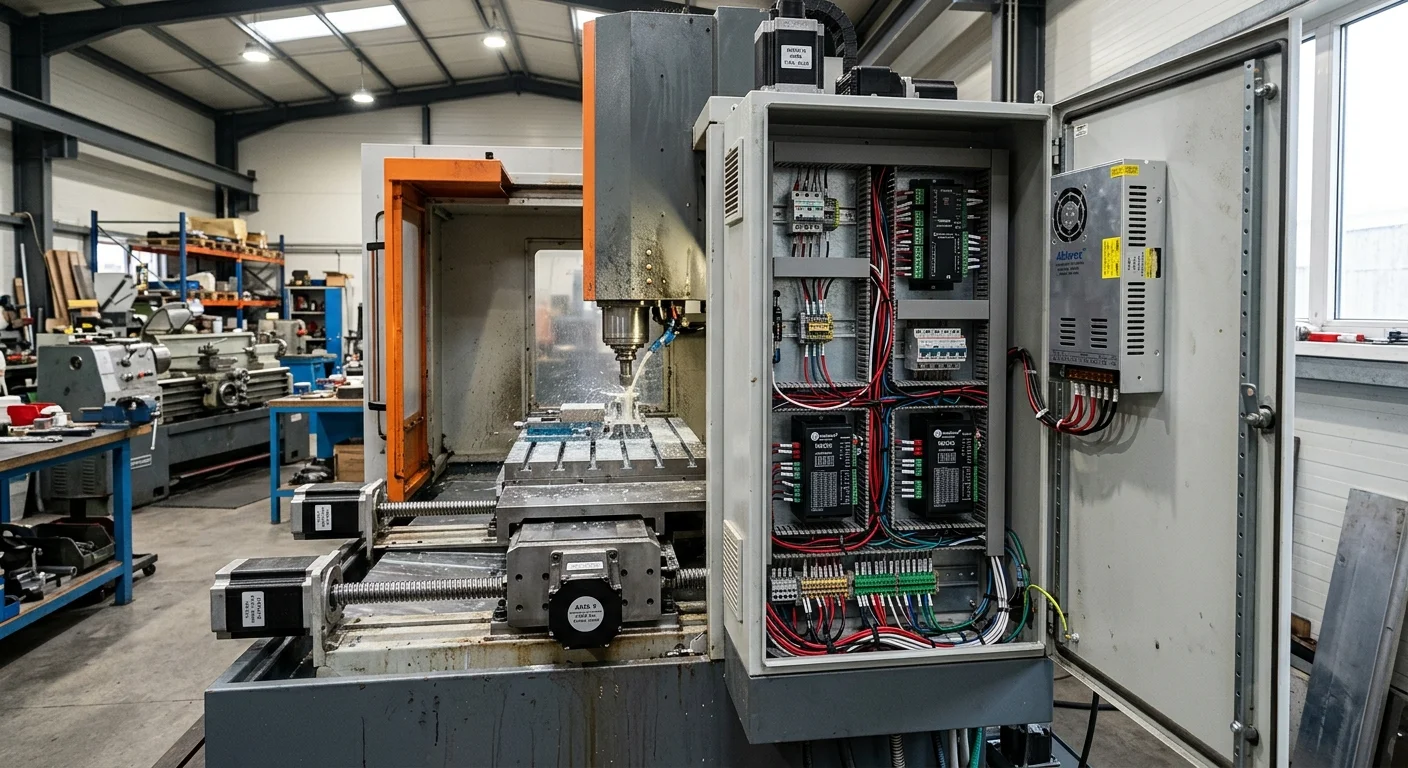
Cabinet installation considerations
For a CNC machine or robot with multiple axes, the recommended practice is to use a separate power supply for the drive circuits and a separate one for the controller and logic. This isolates switching noise from the drivers and protects the microcontroller from voltage dips during motor startup.
The drive power supply should be protected by a dedicated circuit breaker rated at 125% of the supply's output current. For DIN rail power supplies, mounting in line with breakers and contactors is standard practice.
If the power supply is mounted in a closed enclosure without forced ventilation, check the ambient temperature rating in the datasheet — most models deliver full power up to 40°C, with a 20-30% derating at 50°C.
How to calculate the required power
The total calculated load power is the starting point, but drives require a correction factor. A practical approach:
- Sum the rated currents of all motors (holding current or rated operating current — check the driver datasheet).
- If all motors start simultaneously, multiply the sum by 1.5. If they start sequentially, apply the factor only to the largest motor.
- Add 10-20% for wiring losses and supply derating.
- Select a supply with a power rating at or above the calculated value.
A more detailed approach is described in our article How to Calculate Power Supply Wattage. If the load is complex or mixed — send us the load list and we will size the supply within one working day.