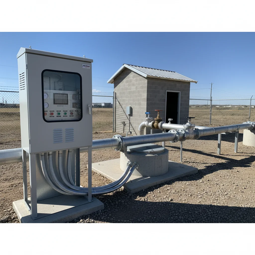
In short, how to set up a frequency converter for a pump (including a borehole pump): pick a drive matched to the pump current with a small margin, wire the 4–20 mA pressure sensor to the analog input, enable PID control and set the pressure setpoint. Then configure sleep mode (so the pump dozes off when there is no demand), current-based dry-run protection and — if needed — torque boost for a long cable. Below we cover each step using verified Veichi AC10, AC01 and AC310 parameters with manual references.
This is an overview hub article. If you need a strictly step-by-step PID walkthrough, see our detailed PID tuning guide for a water pump. If the issue is specifically the 4–20 mA sensor (inversion, feedback fault), jump to the article on connecting a 4–20 mA sensor. Here we put the whole picture together: selection, logic, common pitfalls.
Why a borehole pump needs a VFD
Without a VFD a borehole pump runs on/off: pressure jumps, water hammer hits at start, and the motor takes a 5–7× rated inrush current every time. A frequency converter removes this with three mechanisms:
- Soft start and stop — no water hammer in the pipes, no voltage sag in the grid.
- Stable pressure — PID holds the setpoint whether one tap or five is open.
- Energy saving — the pump runs exactly at the speed needed now, not full-on throttled by a valve.
To be honest: a VFD is not always needed. In the "When you do NOT need it" section below we cover cases where a mechanical pressure tank with a pressure switch is enough.
How to size a VFD for a borehole pump
The main selection criterion is not power but the pump rated current. Pick a drive whose rated output current equals or slightly exceeds the pump motor current. A 10–15% margin is enough: too large a margin worsens current-based protection accuracy (including dry-run).
- Single-phase pump (220 V) — you need a drive with a single/three-phase motor output; for many borehole "Vodoley"-type pumps a capacitor-free scheme is used, where the drive forms the phases itself.
- Three-phase pump (380 V) — the classic, easiest case to set up: a 3×380 V drive matched to the motor current.
- PID + 4–20 mA analog input — a mandatory requirement. The Veichi AC10, AC01 and AC310 series all support this.
Ready models for different currents are gathered in the VFDs for pumps section — with a filter by power and grid type.
PID pressure control: what P, I and D actually do
PID is an algorithm that compares the setpoint pressure with the actual pressure (from the sensor) and adjusts pump frequency to drive the difference to zero. The three terms work like this:
- P (proportional, F13.11) — reaction speed. Pressure drops — how sharply the drive raises frequency. Too high P → the system oscillates. Raise it gently.
- I (integral, F13.12) — accurate convergence to the setpoint. Removes residual error. Do not set it too small for systems with a small tank.
- D (differential, F13.13) — reacts to rate of change. In water supply it is almost always harmful (amplifies sensor noise). Recommended value — 0.
Important: which register is P, I, D on Veichi
This is the most common commissioning mistake. On Veichi AC10, AC01 and AC310, parameter F13.07 is NOT proportional gain — it is "PID control selection" (feedback characteristic: positive/negative). The actual P/I/D coefficients live in F13.11–F13.13. If you have seen a "P=F13.07, I=F13.08" scheme somewhere, it belongs to a different firmware or series and does not apply to the Veichi F-group. Use the table below.
Feedback characteristic: positive or negative
For constant-pressure water supply, F13.07 needs the positive characteristic: when pressure (feedback) exceeds the setpoint, frequency drops and the pump slows. If you see the opposite (more rpm → more pressure, the system races to the ceiling), either the sensor polarity is swapped or F13.07 is set to negative. This scenario, together with 4–20 mA analog inversion, is covered in detail in the separate 4–20 mA sensor article.
The same parameter F13.07 also sets, in its "0000" digit, the differential regulation attribute — differentiate the deviation or differentiate the feedback. For water supply this is not critical since we keep D at zero, but it is worth knowing about: changing F13.07 wholesale by accident can flip the characteristic and break the entire logic.
How it works physically: an oscillation example
Imagine a system with a 3.0 bar setpoint. Someone opens a tap and pressure sags to 2.6 bar. The proportional term (P) immediately adds frequency in proportion to the 0.4 bar difference. If P is too high, the drive overshoots 3.0 bar and pushes pressure to 3.4 bar — then sharply backs off again, and round it goes: classic oscillation, the pump hums, the gauge bounces. The integral term (I) accumulates the small residual difference over time and smoothly brings pressure exactly to 3.0 bar with no overshoot. That is why the correct tuning order is to first find a stable P (so it does not oscillate), then reduce the I time to an acceptable convergence speed. We leave D alone in water: it reacts to sensor noise and only worsens stability.
Sleep mode: so the pump does not run into a dead end
When all taps are closed, PID still tries to hold pressure and runs the pump at low frequency against a wall. This heats the water inside the pump housing and wastes mechanical life. Sleep mode solves it: as soon as demand disappears, the drive smoothly stops the motor and wakes it back up when pressure falls.
On Veichi, the sleep function is the F13.29–F13.33 group (not F13.11/F13.12 as sometimes claimed). Key parameters:
- F13.29 — sleep mode enable (0 = off, 1 = on).
- F13.30 — sleep frequency. The manual default is 10.00 Hz, but that is usually too low for a pump: the recommended practical value is 30–35 Hz (a deliberate change from the default). The pump sleeps when PID drops frequency below this threshold.
- F13.31 — sleep delay: how long to hold low frequency before sleeping (to avoid sleeping on a brief tap closure).
- F13.32 — wake-up deviation: how far pressure must drop below the setpoint to wake the pump. Note: the value is entered as a percentage of the sensor range (default 5.0%, range 0–50%), not in bar directly. Practical delta — 0.5–1.0 bar; for a 0–10 bar sensor that is 5.0–10.0%.
Field tip: if the pump sleeps and immediately wakes (short cycling), the system is too sensitive. Increase the sleep delay F13.31 and wake deviation F13.32, and make sure the pressure tank is not oversized. Short sleep-start cycles wear the pump more than continuous running: each start is a mechanical and electrical load.
Wake-up logic is tied to the feedback characteristic. With the positive characteristic, the pump wakes when pressure falls below the setpoint minus the F13.32 delta. So with a 3.0 bar setpoint and a 0.8 bar delta, the pump sleeps after building pressure and closing taps, and wakes when system pressure drops to 2.2 bar. This delta is matched to the real pressure-tank volume: a small tank empties faster, so the delta can be smaller to keep pressure from sagging too deep.
Current-based dry-run protection
When the borehole runs dry, the pump spins with no water: load drops, and so does the current it draws. This is the basis of the most reliable protection without extra sensors — by load loss.
On Veichi this is done through the load-control group F10.32–F10.36 (underload warning + action). The logic: set a current threshold below the working value (roughly 50–60% of the pump working current) and a hold time. Water column gone → current drops below threshold longer than the set time → the drive stops and raises a warning. Cheaper and more reliable than float switches that foul and stick.
Hack: first run the pump at the nominal mode and read the actual current on the drive display. Set the underload threshold from that real figure, not from the motor nameplate.
The second important detail is the hold time. If you set it too short, the drive will stop the pump on every brief current dip. In practice allow a few seconds: real dry-run will clearly show up in that time, while false trips are filtered out. The trip action (stop / warning) is set by parameter F10.32 itself via its LED digits — for a borehole, stopping makes sense so as not to cook the pump dry.
Note: current-based protection does not replace common sense about the water level in the borehole. If the borehole yield is lower than the pump capacity, the pump will periodically draw water faster than it recharges — beyond current protection, plan a recovery pause for the level to restore.
Pressure tank: why a big tank hurts
It feels intuitive that a bigger tank is better. With a VFD it is the opposite. The optimal volume for PID work is 2–24 L. A tank of 100 L or more makes the system sluggish: pressure changes so slowly that PID cannot hold ±0.1 bar accuracy, and sleep mode starts to drift. A small tank is needed only as a pulsation damper and a wake-up buffer.
| Pressure tank volume | Behaviour with a VFD |
|---|---|
| 2–24 L | Optimal: damper + smooth wake-up, PID holds accuracy |
| 50 L | Acceptable but more sluggish; sleep mode gets finicky |
| 100 L and more | Not recommended: sluggish system, hard to hold ±0.1 bar |
Long cable to the borehole: torque boost
A borehole often means 50, 80, 100 metres of cable. Over that length the voltage drop eats into the starting torque, and the pump may fail to break away or start with a jerk. Fixed with torque boost F04.01. By default F04.01 = 0.0%, which is automatic torque boost — the drive compensates stator-resistance losses on its own. If automatic mode is not enough for a confident start on a long cable, set a fixed value of 2–5%. Do not overdo it: excess torque at low speed heats the motor. Raise it gradually until the start is confident.
Separately, make sure the cable cross-section matches the current and length — no boost compensates for an undersized cable.
Another practical point on long cables is the carrier frequency. Over 80–100 m, a high carrier frequency amplifies capacitive leakage currents and can cause false protection trips or whine. If the drive throws current faults on a long cable, try lowering the carrier frequency a bit. A borehole pump does not need an ultra-high carrier — unlike quiet indoor ventilation.
Parameter summary (Veichi F-group)
All values below are recommended starting points for a borehole pump. Fine tuning is always matched to the specific system. The registers are identical across AC10, AC01 and AC310.
| Parameter | Purpose | Recommended value | Series (same register) |
|---|---|---|---|
| F13.07 | PID control selection (feedback characteristic) | Positive characteristic | AC10 / AC01 / AC310 |
| F13.11 | Proportional gain P1 | Tune gently (too high → oscillation) | AC10 / AC01 / AC310 |
| F13.12 | Integral time I1 | Accurate pressure convergence; not too small | AC10 / AC01 / AC310 |
| F13.13 | Differential D1 | 0 (for water supply) | AC10 / AC01 / AC310 |
| F13.29 | Sleep mode enable | 1 (on) | AC10 / AC01 / AC310 |
| F13.30 | Sleep frequency (default 10.00 Hz) | 30–35 Hz (deliberate change from default) | AC10 / AC01 / AC310 |
| F13.31 | Sleep delay | Tune (against short cycling) | AC10 / AC01 / AC310 |
| F13.32 | Wake-up deviation (% of sensor range) | delta 0.5–1.0 bar; for a 0–10 bar sensor that is 5.0–10.0% | AC10 / AC01 / AC310 |
| F10.32–F10.36 | Load control / dry-run protection | threshold 50–60% working current + time | AC10 / AC01 / AC310 |
| F04.01 | Torque boost (cable 50 m+); default 0.0% = auto | 2–5% (fixed, if auto is not enough) | AC10 / AC01 / AC310 |
Step-by-step PID setup (HowTo)
- Enter the motor nameplate parameters (power, current, frequency) — basic setup is described in the Veichi setup guide.
- Connect a 4–20 mA pressure sensor to the analog input and set the sensor range (e.g. 0–10 bar).
- Enable the PID setpoint source and set the target pressure (e.g. 3.0 bar).
- In F13.07 select the positive feedback characteristic.
- Set starting P (F13.11) and I (F13.12), leave D (F13.13) at 0. Start the pump and open a tap.
- Watch the pressure: oscillating → reduce P; slow to reach the setpoint → reduce the I time. Do it in small steps.
- Configure sleep mode: F13.29=1, sleep frequency F13.30 in the 30–35 Hz range (default is 10.00 Hz — this is a deliberate increase), wake-up delta F13.32 at 0.5–1.0 bar (for a 0–10 bar sensor that is 5.0–10.0% of the range).
- Measure the working current and set dry-run protection (F10.32–F10.36) to 50–60% of it.
- For cable 50 m+, if the start is heavy, set torque boost F04.01 to 2–5% (default 0.0% = automatic mode).
When you do NOT need a VFD
Honestly: not every borehole needs a PID drive. A mechanical pressure tank with a pressure switch is enough if:
- You have one or two consumers and rare draw — pressure accuracy is not critical.
- The budget is tight and the pump is small: the drive cost will not pay back in savings.
- The pump already runs stably, there is no water hammer, and the grid tolerates direct starts.
A VFD pays off where there are many draw points, a requirement for stable pressure, a long cable or a weak grid. If in doubt — send us the borehole and pump parameters, and we will advise whether it makes sense.
Conversely, there are cases where a VFD is almost mandatory: when the grid is weak and neighbours complain about lights flickering at every pump start; when the pipes are old and water hammer has already caused leaks; when the borehole is deep, the cable is long, and a direct start causes a sag that sometimes prevents the pump from starting at all. In such systems, soft start and PID pay back not only in electricity savings but in extended pump and plumbing life.
FAQ
Which VFD suits a borehole pump?
Choose by pump current and power with a small margin, with PID support and a 4–20 mA analog input. For residential and farm boreholes, the Veichi AC10, AC01 and AC310 series work well — they share the same F-group logic. Ready models are in the VFDs for pumps section.
Why does the pump race instead of holding pressure?
Two typical causes: swapped 4–20 mA sensor polarity, or F13.07 set to the negative feedback characteristic instead of positive. Check sensor polarity and the F13.07 characteristic. Full breakdown is in the article on the 4–20 mA sensor and signal inversion.
What does the E.PID error on the display mean?
E.PID is a PID feedback loss: the drive receives no signal from the sensor. Check the analog input (AI2) wiring, sensor integrity, and whether the signal source is selected correctly. The cause is often trivial — a break or a poor terminal in the 4–20 mA loop.
Why does the pump not switch off even though pressure is reached?
Most likely sleep mode is not active or the sleep frequency F13.30 is set too low. Enable F13.29=1, raise F13.30 to 30–35 Hz and check that the wake-up delta F13.32 is not zero. An oversized pressure tank can also prevent the pump from reaching the sleep threshold.
Which pressure tank should I use with a VFD?
A small one — 2–24 L. It is needed only as a pulsation damper and a wake-up buffer. Large tanks (100 L+) make the system sluggish and stop PID from holding accurate pressure.
How to protect the pump from dry-run without a float?
By current drop. Set load control (F10.32–F10.36) to a threshold of 50–60% of the real pump working current plus a hold time. Water gone — current drops — the drive stops. More reliable than float switches that stick.