The main application of frequency converters is usually pumps. Whether surface or submersible, they serve to supply water. But for optimal use, a frequency converter is required. When the VFD operates together with a pressure sensor, the first thing we do is normalize the pressure. Stabilized pressure ensures controlled water consumption—preventing excessive use. As practice shows, water savings with such a system are around 10%. In this application there is also direct electricity savings. According to real data, energy savings reach up to 30%.
Setting up AC310, AC10, AC01 drives for a pressure sensor (PID controller). We will use a pressure sensor with an analog 4–20 mA signal.
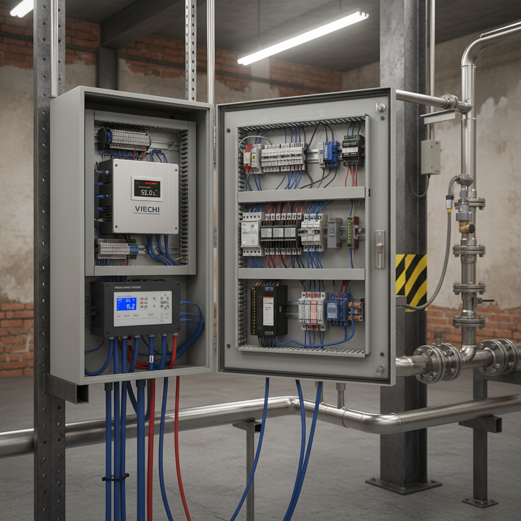
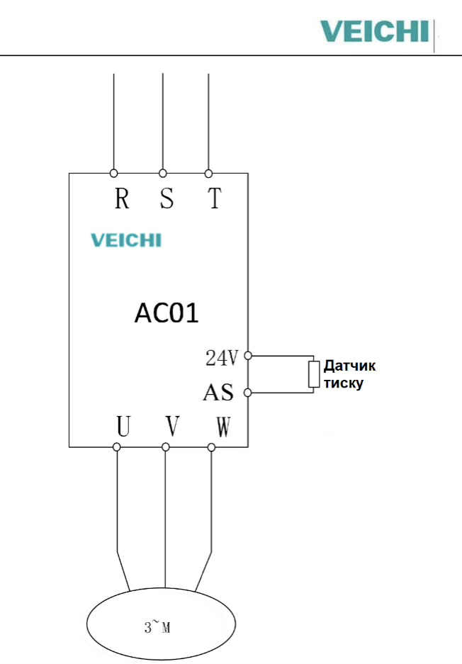
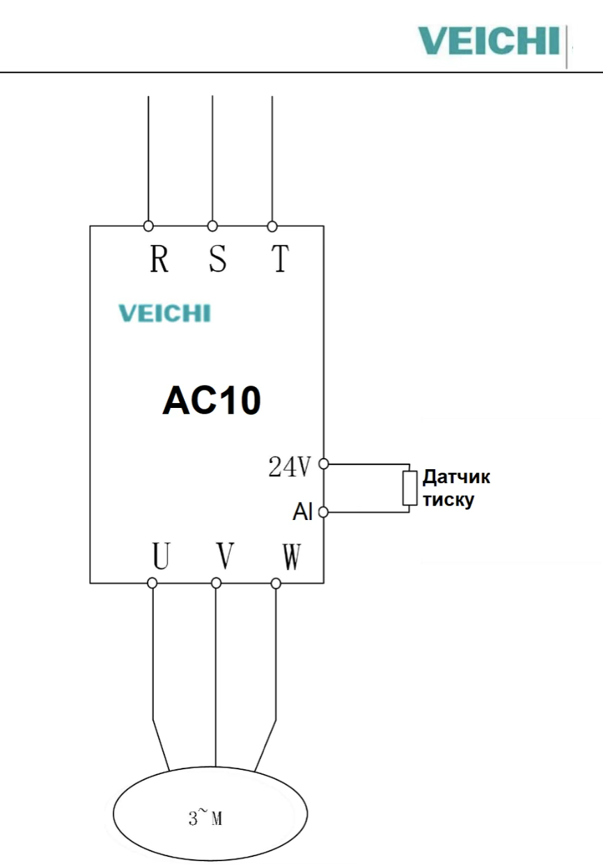
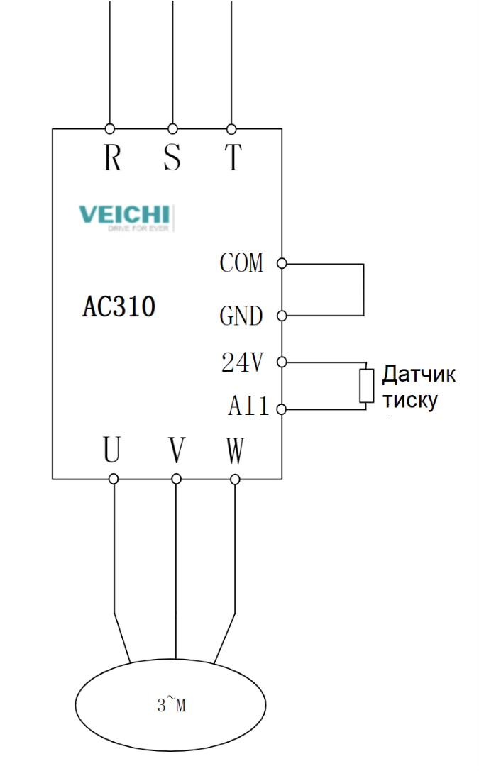
Wiring diagrams for different series
- AC01 series
- AC10 series for power ratings 0.7–5.5 kW
- AC10 series for power ratings 5.5–22 kW


AC310 series
The wiring is done. Now let’s move on to the parameters. We present the parameters in a table. The parameters are the same for all of the above series, which is an unquestionable advantage of VEICHI frequency converters.
| Parameter | Description | Value | Note |
| F00.03 | Reset to factory settings | 22 | |
| F02.01 | Number of motor poles | Value from the motor nameplate, or 3000 rpm — 2, 1500 rpm — 4, 1000 rpm — 6, etc. 2 × (3000 / motor rpm) | |
| F02.02 | Motor rated power, kW | Value from the motor nameplate | |
| F02.03 | Motor rated frequency, Hz | Value from the motor nameplate | |
| F02.04 | Motor rated voltage, V | Value from the motor nameplate | |
| F02.05 | Motor rated speed, rpm | Value from the motor nameplate | |
| F02.06 | Motor rated current, A | Value from the motor nameplate | |
| F02.07 | Motor auto-tuning |
| |
| F01.01 | VFD start method | 0 |
|
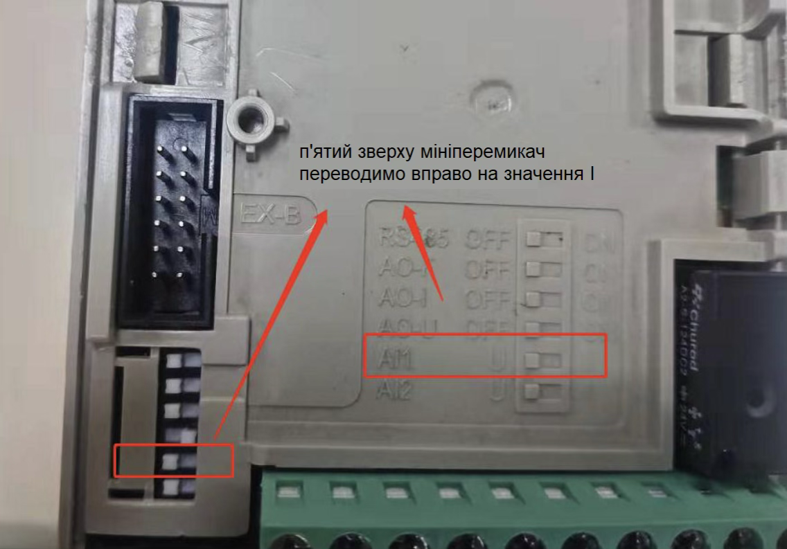
| F01.02 | Frequency command channel | 8 | PID control |
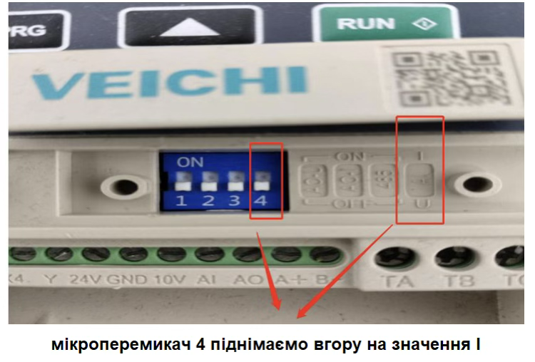
| F05.50 | Lower threshold of analog signal, % | 20.00% | 20% equals 4 mA |
| F07.06 | Auto-restart after power loss/return | 2 |
|
| F07.07 | Time after power-on, s | 0.00 | For this mode, set 0.00 |
| F13.00 | Pressure setpoint source | 0 | Set from keypad |
| F13.01 | Pressure value, % | 30.0% | Set in %. 100% is the permissible pressure of the sensor. If the sensor is 0–10 bar, then 30% is 3 bar. |
| F13.03 | PID feedback signal source | 2 | 2. Current input |
| F13.25 | Reaction to pressure sensor break | 1 | Stop and alarm indication |
| F13.28 | Sensor lower signal value, % | 15.0% | Approximately 3 mA |
| F13.29 | Sleep mode activation | 1 |
|
| F13.30 | Sleep frequency, Hz | 20.00 | Select a value at which the pump delivers a minimal flow |
| F13.31 | Pump run time before entering sleep, s | 1 | Preferably set to the minimum to avoid unnecessary power consumption |
| F13.32 | Deviation magnitude for wake-up, % | 5% | Set in % — the value below the setpoint at which the pump turns on (hysteresis magnitude) |
| F13.33 | Time before exiting sleep mode, s | 1.0 |
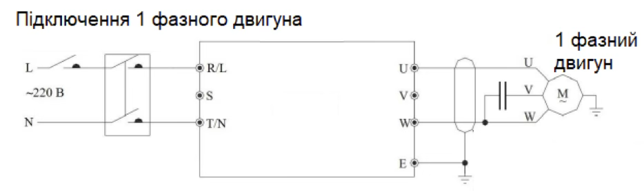
Features of using a VFD with a single-phase motor
- For the case of using a single-phase (1-ph) motor, connect the motor to the VFD output terminals U and W. Do not disconnect the capacitor from the motor.
- Do not change parameter F02.07 (leave 0 — do not perform auto-tuning). Additionally, set parameter F10.20 to 0020(020) — change the last digit from 1 to 0)
System operation check
- After entering the parameters and starting operation, hold the PRG button until C00 lights up (monitoring parameter group). Select parameter C00.09.
- This parameter displays the system pressure (the sensor value). Parameter C00.08 shows the set pressure value.
- The set pressure value is configured in parameter F13.01.
Possible problems and their solutions
1. While the pump is running, C00.09 always shows 0, although there is pressure in the system
- First, go to parameter C00.16 — this is the analog input monitor.
- The sensor may be installed incorrectly, clogged, the connection wires may be damaged, or the pressure sensor may be faulty.
2. The frequency on the display increases slowly
- This occurs when the set and actual pressure differ only slightly. The greater the difference, the faster the frequency increases.
3. Not enough water during peak demand
- Make sure the pump is running at rated frequency.
- Make sure the water supply is not blocked.
- Air may have entered the system; take measures to remove it.
- Ensure the installed pump matches your draw-off requirements; if necessary, replace the pump and VFD with more powerful ones.
4. The VFD runs continuously and does not enter sleep mode
- Parameter F13.29 is not set to 1
- The motor operates in a range higher than specified in parameter F13.30
- There may be a continuous water consumption or a leak
5. The VFD frequently starts/stops
- The VFD switches off — pressure instantly drops. It switches on — quickly builds pressure and switches off again. A “short” system and a powerful pump.
- As an option, install a hydraulic accumulator to increase the system volume.
- Pressure sensor damage