A VFD for a single-phase motor: why the Veichi AC01
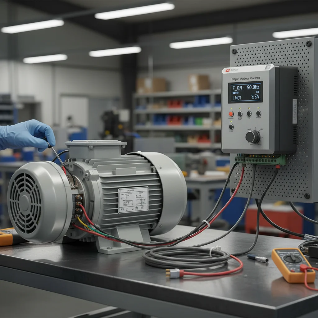
A VFD for a single-phase motor solves what capacitor starting cannot: a smooth ramp, speed control and a soft start for a single-phase pump or a small 220 V motor. A convenient drive for this is the single-phase VFD Veichi AC01 — a compact mini-drive for a single-phase 220 V input. Below is how to wire a single-phase motor (including a "Vodoliy" pump without a capacitor) and set up the AC01, with parameters verified against the official manual for this exact series.
Basic startup of the AC01 comes down to four steps: enter the motor nameplate data into the drive (group F02), choose the run channel (keypad or terminals, F01.01), choose the frequency reference source (F01.02), and go through the protections once. For a single-phase pump there is one more key step — wiring the windings without a capacitor and disabling phase-loss protection. The codes and terminals here differ from the AC10/AC310, and that difference is where half of first starts fail.
The AC01 in the S2 variant is a single-phase drive for a 200–240 V input. Typical applications: single-phase "Vodoliy" pumps, small single-phase motors, household and light industrial machinery, and replacing capacitor starting with electronic control. If you have an AC10 or AC310, the parameters differ in part — see the separate Veichi setup guide. To pick a model for your mechanism, see the single-phase 220V drives.
Step 1. Motor nameplate data (group F02)
Any AC01 setup starts not with frequency but with the motor nameplate. The inverter builds its whole control model around these numbers, and if the ratings are entered "by eye", you get either weak low-speed torque or overheating. Fill in group F02 exactly as written on the motor plate:
- F02.04 — rated speed, rpm. That is speed, not voltage — a common point of confusion.
- F02.05 — rated motor voltage, V. The same parameter plays an extra role on single-phase installations (the ≤253 V limit is below).
- F02.06 — rated motor current, A. The drive computes overload against it, and it is what you compare the running current to after start.
Tip. After entering F02, run auto-tuning (F02.07): "2" is static (shaft not turning), "1" is rotary (shaft spins freely, no load). The drive measures the winding resistances and gives noticeably more stable low-speed torque. For a single-phase motor without a capacitor you usually cannot spin the shaft freely, so use the static option.
Step 2. Run channel: keypad or terminals (F01.01)
By default the AC01 starts from the button on the external keypad. In a real installation you more often need an external button or an automation signal — that is parameter F01.01 (Command source):
- F01.01 = 0 — keypad control (external panel);
- F01.01 = 1 — via terminals (X1–X3);
- F01.01 = 2 — via RS485.
Terminal tip. In Veichi drives the digital-input logic returns to the COM terminal, not to GND. GND is reserved exclusively for analog signals. So route the common wire of the Start/Stop buttons to COM — this is the most common mistake when first wiring external control on the AC01.
An AC01 specific: the current version of the drive has no built-in keypad — an external panel KBD300-25 or KBD01-15 connects through the RJ45 port. RS485 on terminals A+/B- and the external panel on RJ45 are one physical port and cannot work at the same time. If you connect the panel with power off, the AC01 detects it automatically, and Modbus on that port becomes temporarily unavailable.
Step 3. Frequency source: AS and VS inputs — the AC01's key difference
Speed is set by F01.02 (Frequency source A). Here is the AC01's key difference from the higher series: on the AC10/AC310 the analog inputs are called AI1/AI2, while on the AC01 they are called AS and VS — physically different terminals with different names.
- AS — current analog input, 0–20 mA / 4–20 mA (this is where the 4-20 mA pressure sensor goes);
- VS — voltage analog input, 0–10 V (an external potentiometer goes here).
So the F01.02 values on the AC01:
- F01.02 = 0 — digital keypad setting (handy for the first test run);
- F01.02 = 1 — keypad potentiometer;
- F01.02 = 2 — current analog input AS;
- F01.02 = 3 — voltage analog input VS;
- F01.02 = 6 — via RS485;
- F01.02 = 8 — via PID (for pressure-controlled pumps).
Where errors come from. Someone sees "set F01.02 = 2 for analog" on a forum from an AC310 user and applies it on the AC01. The value matches, but on the AC310 "2" is input AI1, while on the AC01 "2" is the current input AS. If the signal is physically wired to VS (voltage), the drive "sees" no reference. For a 0–10 V external potentiometer on the AC01 the correct value is F01.02 = 3 (VS), not "2".
Step 4. Connecting a single-phase "Vodoliy" pump without a capacitor
This is the most requested AC01 scenario: running a single-phase "Vodoliy" pump or similar mechanism from the drive after removing the run capacitor. The drive's electronics form a rotating field better than a capacitor phase shift, so starting becomes smoother. But the procedure has a strict order.
4.1. Identify the windings with a multimeter
A capacitor single-phase motor has three leads: common, main (run) winding, and auxiliary (start) winding. Before wiring, measure the resistance between the leads:
- Common: has continuity (resistance) to both of the other leads.
- Main (run) winding: has the lower resistance.
- Auxiliary (start) winding: has the higher resistance.
4.2. Wire to U-V-W
Remove the run capacitor and connect the three wires to the AC01 power output as follows:
| Motor lead | How to identify | AC01 terminal |
|---|---|---|
| Main (run) winding | lower resistance | U |
| Common | continuity to both | V |
| Auxiliary (start) winding | higher resistance | W |
4.3. Disable phase-loss protection — on the AC01 it is F10.20
Here is an important technical point. In single-phase mode without a capacitor the drive "sees" an unbalanced load and may trip on phase-loss protection by default. It must be disabled. On the AC01 this parameter is F10.20 ("I/O phase-loss protection"): the LED "00" digit (input phase-loss protection) must be set to 0 (OFF). This is confirmed by the AC01 manual itself.
An honest caveat for the engineer: some generic Veichi instructions show "F09.13 = 0" to disable this protection. On the AC01 there is no F09.13 for this — the F09 group on the AC01 is reserved for maintenance (fan and relay counters). If you are coming from an AC10, do not carry F09.13 over to the AC01 blindly: here it is F10.20 that works.
4.4. Mode and acceleration
Set scalar control F01.00 = 0 (AM-V/F) — a single-phase motor does not need vector mode. Set a short acceleration time, on the order of the F01.21 group ~1.0 s, to overcome the starting torque quickly.
Reverse and direction of rotation (F07.05)
The direction of rotation on the AC01 is set by F07.05 (Direction). It is a multi-digit parameter: the LED "0" digit controls the direction of rotation (0 — keep, 1 — change direction), and separate digits enable or disable the forward/reverse commands. If the pump or fan spins the wrong way, do not swap the wires at the output — it is easier to change direction via F07.05. Note: a drive initialization (factory reset) does not restore this value.
Carrier frequency (F01.40)
The PWM carrier frequency on the AC01 is set by F01.40 in the range 2.0–12.0 kHz. A higher value means a quieter motor but more heating of the power switches; a lower value means a cooler drive but an audible hum. For household pumps where quiet operation matters it makes sense to raise the carrier; for long cables and harsh conditions, keep it lower.
AC01 parameter summary table
| Parameter | Value | Purpose |
|---|---|---|
| F01.00 | 0 = AM-V/F (scalar) | Motor control mode |
| F01.01 | 0 keypad / 1 terminals / 2 RS485 | Run command source |
| F01.02 | 2 = AS (current), 3 = VS (voltage) | Frequency reference source (AC01 inputs) |
| F02.04 / F02.05 / F02.06 | from nameplate | Rated motor speed / voltage / current |
| F02.07 | 2 static / 1 rotary | Motor auto-tuning |
| F07.05 | LED "0" = 0/1 | Direction / reverse |
| F01.40 | 2.0–12.0 kHz | PWM carrier frequency |
| F10.20 | LED "00" = 0 (OFF) | Disable phase-loss protection (single-phase, no capacitor) |
Step-by-step: basic AC01 startup
- De-energize and check. Before working on the terminals, switch off power and wait 5 minutes — the bus capacitors do not discharge instantly.
- Enter the nameplate into group F02 (speed, voltage, current).
- Run auto-tuning F02.07 = 2 (static) for a standard motor.
- Choose the run channel F01.01 for your scheme (for the first run it is convenient to leave keypad = 0).
- Choose the frequency source F01.02: for a test run, digital from the keypad (0); then for the real scheme — AS (2) for a 4-20 mA current sensor or VS (3) for a 0–10 V potentiometer.
- For a single-phase motor — identify the windings, wire U-V-W (main-common-auxiliary), remove the capacitor, and disable phase-loss protection F10.20 (LED "00" = 0).
- Check direction at low frequency; change it via F07.05 if needed.
- Apply the working mode and monitor the motor current — it must stay within the nameplate rating.
Safety and application limits
De-energize before working. The AC01 carries dangerous voltage. Do not wire under power: switch off all related equipment and wait 5 minutes until the DC bus voltage drops to a safe level. Grounding resistance should be below 10 Ω.
Keep the mains ≤253 V. For single-phase applications, do not set F02.05 (rated voltage) above 253 V. The drive is not a stabilizer, and exceeding the limit can damage the capacitors. The practical mains guideline is no higher than ~253 V.
The main limit of the single-phase scheme. The Capacitor-Free method does not work with every motor. After you have removed the capacitor and started the motor, measure the running current. If it exceeds the motor's rated current by more than two times, stop operation: such a motor is not suitable for drive operation and must be replaced with a three-phase one. This is an honest limit of physics — genuine single-phase motors with separate start and run windings cannot be driven well electronically, and no parameters will "force" them.
If the AC01 shows a fault code during start, check the reference of Veichi error codes (E.OC, E.OV, E.Lu).
FAQ on AC01 setup
How do I connect a "Vodoliy" pump to the AC01 without a capacitor?
Remove the run capacitor. With a multimeter, identify the leads: the common has continuity to both, the main winding has the lower resistance, the auxiliary has the higher. Wire main to U, common to V, auxiliary to W. Set V/F mode (F01.00 = 0), disable phase-loss protection F10.20 (LED "00" digit = 0), and set a short acceleration time (~1.0 s). Check the current after start.
How do I identify single-phase motor windings with a multimeter?
Measure the resistance between all three leads pairwise. The lead that has continuity to both others is the common. Of the remaining two: the lower resistance is the main (run) winding (to terminal U), the higher resistance is the auxiliary (start) winding (to terminal W). The common goes to V.
How do the AS and VS inputs on the AC01 differ from AI1/AI2 on the AC10?
They are different physical terminals with different names. On the AC01, AS is the current input (0/4-20 mA) and VS is the voltage input (0–10 V), selected by F01.02 = 2 (AS) and F01.02 = 3 (VS). On the AC10/AC310 the analog inputs are called AI1/AI2. So you cannot carry an F01.02 value from another series' instructions over blindly.
Which parameter disables phase-loss protection on the AC01 — F09.13 or F10.20?
On the AC01 it is F10.20. There is no F09.13 for this on the AC01 (the F09 group is reserved for maintenance counters). The F09.13 value appears in generic instructions for other Veichi series — it does not apply to the AC01.
Why does the motor hum and not pull after connection?
The most common cause is a missing or wrong nameplate in group F02. Check the rated voltage, current and speed, then run auto-tuning (F02.07). For a hard low-speed start, raising the manual torque boost helps, but you should always start from correct nameplate data.
Which AC01 do I need for a single-phase 220 V mains?
For single-phase 220 V supply, choose AC01 models in the S2 variant (single-phase input 200–240 V). To pick a specific model for your pump or motor, see the catalog of single-phase 220V drives or the Veichi VFDs; for pump tasks — the VFDs for pumps selection. If you need broader context on setting up a borehole pump with PID and sleep mode, see the separate article on a VFD for a borehole pump.
Other Veichi series: Veichi AC10 setup and Veichi AC310 setup.