Where the voltage on the enclosure comes from
A fairly common complaint after installation: voltage "tingles" on the motor housing, the cabinet or the drive itself, while the keypad or sensors start to glitch. This is no mystery — it is a consequence of how the drive forms its output. PWM switching creates high-frequency leakage currents that need somewhere to drain. If the grounding is done wrong, these currents flow through enclosures and signal circuits, producing a "stray" voltage.
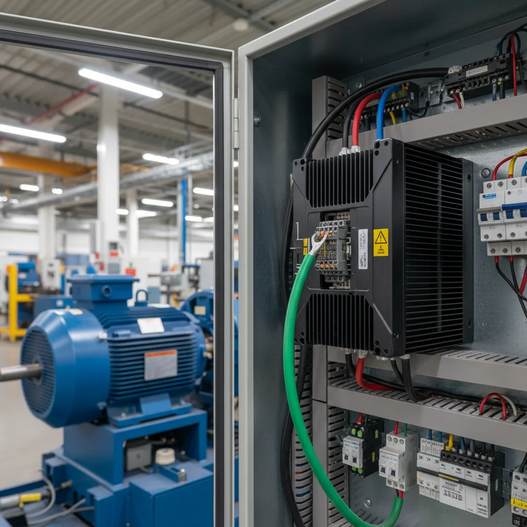
Basic PE requirements on Veichi
The AC10, AC310 and AC01 manuals state it the same way:
- Each device must be grounded through the
E(PE) terminal. - Grounding resistance — less than 10 Ohm.
- Use a dedicated conductor of adequate cross-section for grounding, not the supply "neutral" and not a random nearby metal structure.
This is the minimum without which the rest of the settings will not help: the drive's noise immunity depends directly on the quality of the PE.
Motor PE — straight to the drive
The key installation rule: route the motor's grounding wire directly to the PE terminal of the drive, not to a common building busbar. It might seem that "earth is the same everywhere" — but it is not. When the motor PE sits on a shared busbar together with a dozen other consumers, the PWM leakage currents wander along that busbar and couple into adjacent circuits. A direct "motor → drive PE" connection returns this current by the shortest path back into the drive.
For a shielded motor cable the shield is also brought to PE on the drive side — it is part of the same HF-current return loop. The shorter and more direct the "motor → drive" path, the less interference "creeps" across the cabinet.
A special case is several drives in one cabinet. The temptation to bring all the PE connections to a single shared bar is strong, but this is exactly how "ground loops" are born: leakage currents from one drive couple into the neighbouring ones. The correct approach is a star scheme: each drive with its own conductor to the main grounding point, rather than a series "daisy-chain" connection.
Diagnostics: measuring the "0 — earth" voltage
A simple field test: measure the voltage between the control circuit "zero" (COM/GND) and an independent earth. In our experience, a noticeable voltage — a guideline of more than 5 V — is a sign of a shared grounding loop that needs to be separated. That was the case, for example, with ~20 V on the enclosure: the solution was precisely to split the grounding systems of the power and control sections.
| What we measure | Norm | Action on deviation |
|---|---|---|
| PE resistance | < 10 Ohm | improve the grounding loop, check the connections |
| "0 — earth" voltage | near 0 (guideline < 5 V) | separate the grounding loops of the power and control sections |
How to separate the grounding loops
- Motor PE — with a dedicated conductor straight to the E terminal of the drive.
- Drive PE — to the cabinet's main grounding point, separate from the "dirty" power grounds.
- Do not mix the "earth" of signal circuits (sensor shields) with the power earth — ground it on one side only.
- Avoid "ground loops": one grounding point, not a ring of several.
It is also worth remembering that when braking large inertial masses, energy is returned to the DC bus, and a braking resistor is connected here — this too is part of a "clean" dissipation of energy, not of grounding. More on this in the article on overvoltage and the braking resistor.
The motor cable: a separate matter
A long cable to the motor is an antenna radiating HF interference from the PWM. A few practical rules:
- On critical installations use a shielded motor cable; bring the shield to PE on the drive side around the full perimeter (360°), not as a "pigtail".
- Do not run the motor cable in the same tray as signal and low-current mains lines.
- If the distance to the motor is long, account for the voltage drop: use a cable of adequate cross-section for such a connection (the AC10/AC310 manuals remind you of this directly).
All of this works together with grounding: a shield is useless without a good PE, and a PE without a shielded cable will not save you from pickup on a long line.
What not to do
- Do not use the building busbar as the sole grounding of the motor.
- Do not ground the signal cable shield on both sides — this creates a loop.
- Do not skimp on the PE conductor's cross-section.
- Do not confuse the working supply "neutral" with PE.
A separate piece of advice: do not use the supply "neutral" (neutral N) as a ground. These are different conductors with different purposes. The neutral carries the working current and may have a potential on it, so equipment is grounded only through a dedicated PE conductor to a loop with a resistance of less than 10 Ohm. Substituting the neutral for PE is one of the most dangerous installation mistakes.
If the stray voltage appeared right after replacing a European drive, check the entire transition scheme — the map is in the reference article on migrating to Veichi.
FAQ
What should the grounding resistance be for Veichi?
Less than 10 Ohm — that is the requirement of the AC10, AC310 and AC01 manuals. Higher resistance worsens the dissipation of leakage currents and the noise immunity.
Why can't I bring the motor PE to a common busbar?
Then the HF leakage currents wander along the busbar and couple into adjacent circuits. A direct connection to the drive's PE terminal returns these currents to the drive by the shortest path.
The enclosure "tingles" with current — is that dangerous?
Yes, it is an alarm signal. A noticeable voltage appearing on the enclosure means the grounding is done wrong or has too high a resistance. You must not operate equipment in this state: first bring the PE up to standard (resistance <10 Ohm, direct motor connection) and separate the loops.
Will a line or motor reactor help?
A reactor reduces the steep edges and, accordingly, the level of interference, but it does not replace proper grounding. First — a correct PE and separated loops, and only then a reactor as an additional measure if the line to the motor is long.