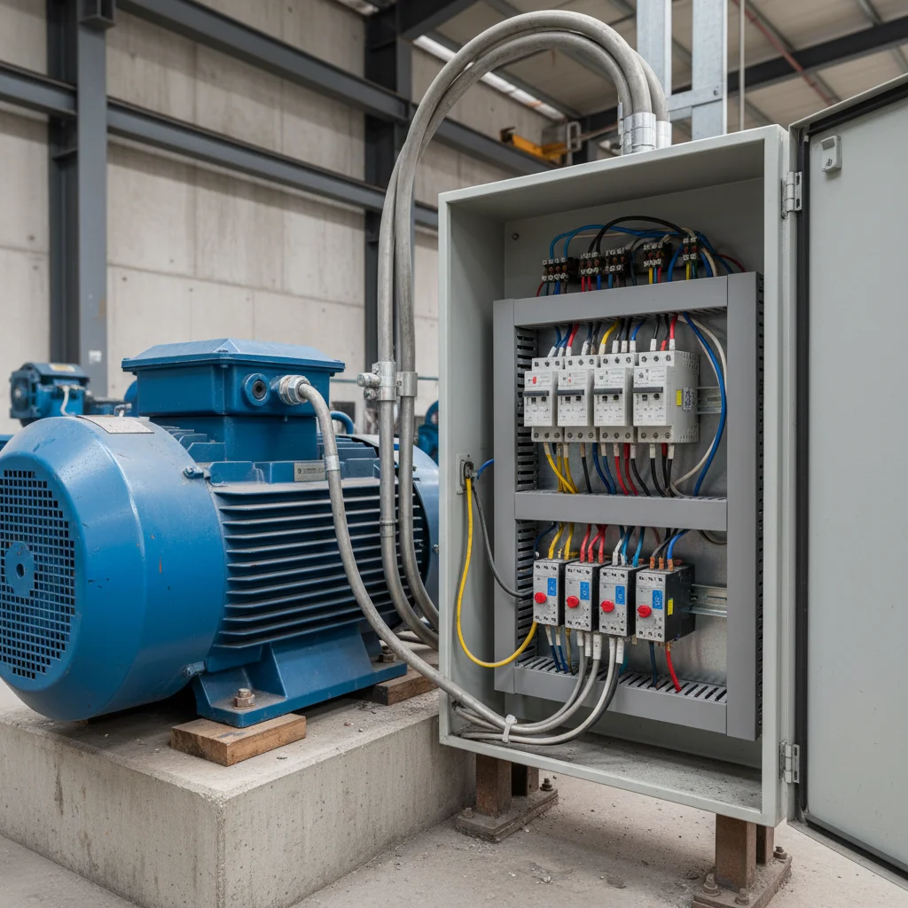
Three-phase asynchronous electric motors are the basis of industrial production, construction sites, and powerful private workshops. Their popularity is due to high reliability, simple design, and an excellent efficiency factor. However, for the motor to operate for a long time, efficiently, and safely, it must be correctly connected to a three-phase 380 V network. Incorrect connection can lead not only to the failure of the unit itself but also to damage to equipment and the creation of dangerous situations.
In this article, we will examine in detail all aspects of connecting a three-phase motor. We will analyze two main schemes — "Star" and "Delta", learn to read the motor's nameplate, consider practical connection steps, and talk about mandatory protection measures. This material will be your reliable guide, whether you are an experienced electrician or a home craftsman who is encountering such a task for the first time.
Theoretical foundations and motor nameplate
Before taking up tools, it is extremely important to understand the theory and what equipment we are dealing with. The operation of an asynchronous motor is based on the principle of creating a rotating magnetic field that causes the rotor to rotate. This field is created by three windings located in the stator at an angle of 120 degrees to each other, to which three-phase voltage is applied.
The main source of information about your motor is the metal plate on its casing, which is called the nameplate. The ability to properly "read" it is 90% of the success of a correct connection.
How to read the motor nameplate
The nameplate indicates all key motor parameters. Let's consider the most important ones for connection:
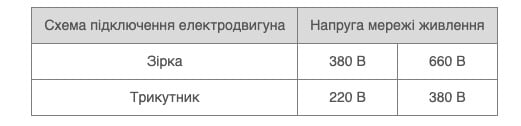
Voltage (V): This is the most important parameter. It is indicated as two values separated by a slash, for example, 220/380 V or 380/660 V. Next to these values, there are often connection scheme icons: Δ/Y (Delta/Star).
The rule is: The lower voltage value corresponds to the "Delta" scheme, and the higher one to the "Star" scheme.
If the nameplate says Δ/Y 220/380 V, it means that for operation in a 380 V network, this motor must be connected according to the "Star" (Y) scheme. If connected as "Delta" to a 380 V network, it will burn out because its windings are designed for 220 V.
If the nameplate indicates Δ/Y 380/660 V, then for operation in our standard 380 V network, it should be connected according to the "Delta" (Δ) scheme. This will allow the motor to achieve maximum power. Connection according to the "Star" (Y) scheme is also possible, but the motor will operate at reduced power and will not be able to reach nominal parameters under load.
Power (kW): Shows the useful mechanical power on the motor shaft.
Nominal current (A): The current drawn by the motor from each phase at nominal load. This value is needed to select protective equipment (circuit breaker and thermal relay).
Rotation speed (rpm): The rotational speed of the motor shaft.
Efficiency (%): Efficiency factor, showing the effectiveness of converting electrical energy into mechanical energy.
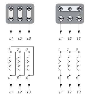
Fig.1. Connecting a three-phase electric motor using "delta" and "star" schemes

Connection schemes: "Star" and "Delta"
As we have already found out, there are two main configurations for connecting stator windings. The choice of scheme depends solely on the motor's design (its nominal voltages) and the voltage of your network.
"Star" (Y) scheme
When connected in "Star," the ends of all three windings (conventionally denoted as C4, C5, C6 or U2, V2, W2) are connected at a single point, called the neutral point. And the three phases of the network L1, L2, L3 are applied to the beginnings of the windings (C1, C2, C3 or U1, V1, W1).
Features of the "Star" scheme:
Smooth start: The motor starts more smoothly, and starting currents are significantly lower than in "Delta."
Reduced voltage on windings: Each individual winding receives not the line voltage of 380 V, but the phase voltage, which is √3 times less (380 V / 1.73 ≈ 220 V).
Application: This scheme is used for motors with a nominal voltage of 220/380 V in a 380 V network. This is the standard and safe way to connect such motors.
"Delta" (Δ) scheme
When connected in "Delta," the windings are connected in series: the end of the first winding is connected to the beginning of the second, the end of the second to the beginning of the third, and the end of the third to the beginning of the first, forming a closed delta. The three phases of the network L1, L2, L3 are connected to the connection points of the windings.
Features of the "Delta" scheme:
- Maximum power: The motor develops its full, nominal power.
- High starting currents: The starting current can exceed the nominal by 5-7 times, creating a large load on the network and mechanical parts.
- Full voltage on windings: Each winding receives the full line voltage of the network — 380 V.
Application: This scheme is used for motors with a nominal voltage of 380/660 V when connected to a 380 V network. This allows you to "squeeze" the maximum out of the motor.

Comparative table of connection schemes
| Characteristic | "Star" (Y) Scheme | "Delta" (Δ) Scheme |
| Voltage per winding (in 380 V network) | ~220 V | ~380 V |
| Starting current | Moderate | High (√3 times higher than "Star") |
| Power | Reduced (approximately 30-50% of nominal for a 380/660 motor) | Nominal (maximum) |
| Smoothness of operation | High, soft start | Lower, sharp start |
| Recommended application (in 380V network) | For 220/380 V motors | For 380/660 V motors |
Practical guide to connecting to a 380 V network
Let's move from theory to practice. The connection process consists of several important steps.
Step 1: Safety and preparation
ATTENTION! All connection work must be carried out only after complete de-energization of the line. Turn off the corresponding circuit breaker in the distribution panel and ensure there is no voltage using a multimeter or voltage indicator on all three phases.
Prepare tools and materials:
- Set of screwdrivers and wrenches.
- Insulation stripper and crimping tool.
- Multimeter.
- Power cable of appropriate cross-section (cross-section is selected depending on motor power and line length).
- Cable lugs.
- Protection devices: three-pole circuit breaker and magnetic starter with thermal relay.
Step 2: Connection in the terminal box (bore)
Open the terminal box cover on the motor. Inside you will see six terminals arranged in two rows. They may be labeled as U1, V1, W1 (top row) and W2, U2, V2 (bottom row) or C1-C6. These are the leads of the three stator windings.
Special copper or brass jumpers, usually supplied with the motor, are used to connect the terminals.
"Star" scheme connection:
Install the jumpers so that they connect three terminals in one row (usually W2, U2, V2). This creates the neutral point. Connect the three phase conductors of your power cable (L1, L2, L3) to the other three terminals (U1, V1, W1). Screw the fourth conductor (grounding, PE) to the special grounding bolt on the motor casing.
"Delta" scheme connection:
Install three jumpers vertically, connecting terminals in pairs: U1 with W2, V1 with U2, W1 with V2. Do not forget to connect phases L1, L2, L3 to these three connected pairs of terminals. The grounding conductor, as in the previous case, is attached to the casing.
Step 3: Motor protection
Simply connecting the motor to the network is not enough. It is necessary to ensure its reliable protection from overloads, short circuits, and other emergency modes. For this, a set consisting of a circuit breaker and a magnetic starter with a thermal relay is used.
Circuit breaker (CB): Installed at the beginning of the line and protects the cable and motor from short-circuit currents. It must be three-pole. Its rating is selected slightly higher than the motor's nominal current.
Magnetic starter with thermal relay: This is the main device for protection. The starter provides remote control ("Start"/"Stop" buttons), and the thermal relay protects the motor from prolonged overloads. The current on the thermal relay is set 5-10% higher than the motor's nominal current indicated on the nameplate. If the motor is overloaded, the relay will heat up and open the starter's control circuit, disconnecting the motor.
How to change the direction of rotor rotation
Sometimes it becomes necessary to change the direction of rotation of the motor shaft (for example, to reverse a conveyor). With a three-phase motor, this is done very simply. To reverse, you need to swap any two of the three phases connected to the motor. For example, if you had phases L1, L2, L3 connected, to change the direction you need to connect them as L2, L1, L3 (swapped the first and second phases). The third phase does not need to be touched. This is most easily implemented using a reversible magnetic starter.
Conclusions
Proper connection of a three-phase electric motor is the key to its long and trouble-free operation. Let's summarize the key rules:
- Always start with the nameplate: Determine the motor's nominal voltage (e.g., 220/380V or 380/660V).
- Choose the correct scheme for a 380V network: "Star" for 220/380V motors, "Delta" for 380/660V motors.
- Observe safety rules: Work only on a de-energized line.
- Use protection: Installation of a circuit breaker and a magnetic starter with a properly adjusted thermal relay is mandatory.
- Do not forget about grounding: The motor casing must be reliably grounded.
By following these simple but important recommendations, you will be able to connect your equipment independently and safely, ensuring its efficient operation for many years.