Reactive power compensation: what it is and why it lowers your electricity bill
Any plant that runs induction motors, transformers or welding equipment draws two kinds of power from the grid. Active power, which turns into useful work and heat, and reactive power, which merely sloshes back and forth between the grid and the electromagnetic field of the equipment without producing anything. Reactive power does no work, yet it very really loads cables, transformers and your electricity bill. Reactive power compensation removes this ballast closer to the load, and that is exactly what capacitor banks and synchronous machines are for.
The power triangle: active, reactive, apparent
To talk about compensation in concrete terms, you need to understand three quantities. Active power P (kW) does the work. Reactive power Q (kvar) builds the magnetic field in motors and transformers. Apparent power S (kVA) is what actually flows through the cable and what the transformer is rated for. They are tied together by a right-angled power triangle.
| Quantity | Symbol | Unit | Role |
|---|---|---|---|
| Active | P | kW | useful work, heat |
| Reactive | Q | kvar | feeds the electromagnetic field, does no work |
| Apparent | S | kVA | total current in the cable: S² = P² + Q² |
The power factor is cos φ = P / S. The closer cos φ is to unity, the smaller the reactive share and the lower the current in the cable for the same useful work. A plant with cos φ 0.7 loads its cable and transformer roughly 40% harder than the same plant with cos φ close to 1. Hence the money: you pay for the apparent power that your equipment pulls from the grid.
Consumers of reactive power and the contracted cos φ target
Reactive power is consumed by everything that runs on an electromagnetic field. By expert estimates, around 60% of all reactive energy worldwide goes to induction motors and roughly 25% to transformers. The remainder is taken by induction furnaces, welding sets, power lines and choke-ballast lighting.
- induction motors (pumps, fans, compressors, conveyors);
- power and welding transformers;
- induction furnaces and heaters;
- overhead and cable power lines;
- gas-discharge and fluorescent lighting with chokes.
The cos φ target is set not by "the law in general" but by your contract with the distribution system operator (DSO). It is typically held in a range of about 0.92–0.96 (which corresponds to tg φ of roughly 0.25–0.42, since DSO contracts often set the threshold via tg φ), but the exact threshold and billing rules are spelled out in your specific contract and tariff. For reactive power flowing in excess of the contracted value the DSO applies a surcharge to the bill. You should not look for an exact penalty figure in an article: check your own contract and metering acts, because the terms differ for different consumers and voltage classes.
Capacitor banks or synchronous machines
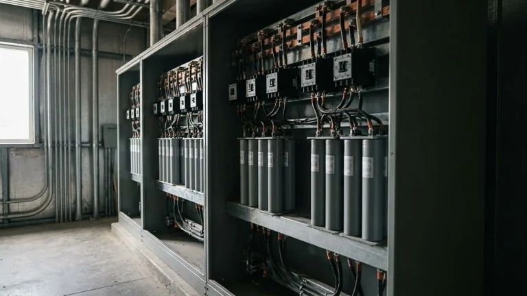
Reactive power is generated where it is consumed, in two ways. Capacitor banks (power-factor-correction capacitors, automatic capacitor banks) deliver capacitive reactive power that offsets the inductive reactive power from motors. This is the most common option at an industrial site: low specific active-power losses, no moving parts, quiet operation, simple installation and automatic control based on the actual cos φ.
Synchronous machines (synchronous motors and synchronous compensators) can also deliver reactive power, and they regulate it smoothly through the excitation current. Unlike a capacitor bank, a synchronous machine works as a motor with a useful load while simultaneously holding the cos φ. It is chosen where a suitable high-power drive is already present and it makes sense to assign it this function. For most sites the practical choice is an automatic capacitor bank near the distribution-board busbars; a synchronous machine is considered as a solution tied to a specific high-power drive.
The VFD and compensation: the key truth that gets skipped
Here lies a mistake that even equipment vendors often make. A variable frequency drive does indeed improve the displacement power factor at its input: on the DC link it keeps the displacement factor close to 1, because the motor is fed from the inverter rather than directly from the grid. Hence the idea that "I will install a VFD and capacitors are not needed". That is not true.
The input diode rectifier of a variable frequency drive draws current not as a smooth sine wave but in pulses, so it injects harmonics into the grid (higher frequencies described by the THD figure). The drive removes the displacement reactive power, but in return it loads the grid with harmonic distortion. In a three-phase drive the 5th and 7th harmonics dominate (those not multiples of three), so with a large number of drives the total THD on the busbars rises, the transformer and cables overheat, and in networks with a large share of single-phase non-linear loads the neutral overheats too and protection trips. In other words, a VFD does not replace a capacitor bank for the network, and with a large number of drives it can actually degrade power quality.
The second trap concerns the capacitors themselves. A plain capacitor bank together with the network inductance forms a resonant circuit. If the network contains harmonics from motor drives, the frequency of this circuit may coincide with the frequency of one of the harmonics, and resonance arises: the current through the capacitors rises many times over and burns them out. That is exactly why in networks with VFDs capacitor banks are fitted with anti-resonance (detuned) reactors. The reactor shifts the natural frequency of the circuit below the harmonics and removes the risk of resonance. As a rule such reactors are selected by p-factor (typically 5.67%, 7% or 14% depending on the harmonic spectrum of the network). The selection of reactors and filters is a separate task; additional reactors and options for drives are covered in our section on VFD accessories.
How to approach compensation in practice
The starting point is not buying equipment but taking measurements. A power-quality analyzer shows the real cos φ, the load profile over a day and the harmonic level (THD). From this data you can see whether you need a fixed bank or an automatic, stepped one, and whether detuned reactors are required because of the presence of VFDs. For drives where the main goal is not compensation but smooth acceleration and energy saving, soft starters and frequency control are considered separately, but power quality still has to be controlled in that case. If you need help selecting a bank, reactors or taking measurements, write to us through the contacts page and we will suggest a solution for your load profile.
Frequently asked questions
What is cos φ and what is its target value?
cos φ (the power factor) is the ratio of active power to apparent power, cos φ = P / S. It shows what share of the current in the cable does useful work. The target is set by the contract with the distribution system operator, typically held within about 0.92–0.96, but for the exact value check your own contract and tariff.
Are there penalties for reactive power?
For reactive power flowing in excess of the contracted value the operator applies a surcharge to the electricity bill. The specific threshold and the calculation formula are spelled out in your contract with the DSO and differ for different consumers, so there is no universal figure here.
Capacitors or a synchronous motor: which to choose?
For most sites an automatic capacitor bank near the distribution-board busbars is the more practical choice: cheaper, quiet, with no moving parts, controlled by the actual cos φ. A synchronous motor makes sense when the site already has a high-power drive that can be assigned the function of generating reactive power.
Does a VFD replace a capacitor bank?
No. The drive improves the displacement power factor at its input, but its diode rectifier injects harmonics into the grid (THD). It does not compensate reactive power for the rest of the network, and with a large number of drives it even degrades power quality. The network needs a separate capacitor bank.
Why are anti-resonance reactors needed?
Capacitors together with the network inductance form a resonant circuit. With harmonics present from VFDs the circuit frequency may coincide with a harmonic, resonance arises, and the current burns out the capacitors. An anti-resonance (detuned) reactor shifts the natural frequency of the circuit below the harmonics and removes this risk.