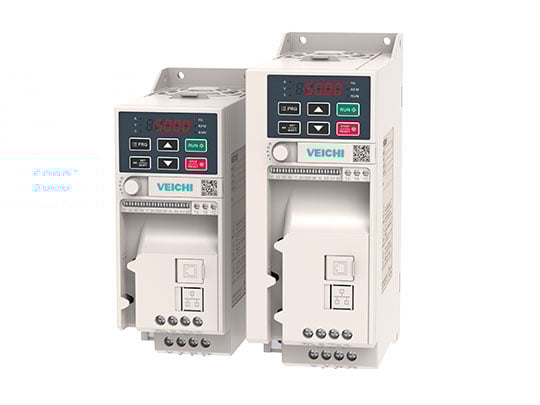
Frequency converter (VFD) – an electronic device that controls the speed and torque of an AC motor by varying the voltage and frequency of the power supply. This allows for precise fan speed regulation for efficient airflow management, increases equipment performance, reduces energy consumption, and minimizes mechanical wear.
When combined with HVAC sensors, the system adjusts fan speed based on air quality: when indicators worsen, speed increases; when they normalize, speed decreases. This way, ventilation ensures a sufficient supply of fresh air with minimal energy costs.
Structure of the electric motor
The electric motor converts electrical energy into rotational movement of the shaft. The shaft transmits rotational force to the working mechanism – for example, the fan impeller or pump.
Speed can be adjusted using a controller. Motors come in both direct current (DC) and alternating current (AC). DC motors have an integrated speed controller, while AC motors require an external controller.
Types of external controllers: transformer-based, TRIAC controllers, frequency converters.
Each type has its advantages/limitations; for AC motors, VFD offers the broadest capabilities.
AC motor: electrical currents and magnetism
The stator houses the coils. Alternating current creates a rotating magnetic field at a speed equal to the network frequency. The rotor “follows” this field:
In synchronous motors – a rotor with permanent magnets.
In asynchronous – a “squirrel cage”; current is induced by the stator field and creates its own field.
Currents and fields generate heat. Overheating is the main enemy of AC motors: potential damage can occur due to internal short circuits. Temperature sensors TK/PTC help, which can be read by the VFD and stop the motor in case of overheating.
Technical specifications of the AC motor
Power supply voltage [VAC]: 1×230, 3×230 or 3×400 – available in the network.
Current consumption [A]: increases with speed and load; the maximum value is shown on the nameplate.
Power [W/kW]: a function of voltage, current, and efficiency; indicated on the nameplate.
Speed [RPM] and torque [N·m]: example – tractor (low RPM, high torque) vs F1 car (high RPM, lower torque).
Different types of speed controllers
Transformer and TRIAC controllers reduce voltage – thereby reducing speed. Transformer-based controllers work stepwise (≈5 steps), TRIAC – smoothly. Their advantage is ease of connection without settings.
Frequency converter also provides smooth control but is more complex to manage, requiring initial parameter setup and opens additional logical capabilities through inputs/outputs.
Frequency converter vs TRIAC controller
The key difference: VFD changes both voltage and frequency. TRIAC cuts voltage with unchanged 50 Hz, lowering torque and potentially causing the motor to stall at low speeds.
VFD maintains U/f = const → optimized voltage, better energy efficiency.
At low speeds, the motor retains almost full torque and operates steadily.
TRIAC creates “non-sinusoidal” voltage → possible noise. VFD with PWM shapes nearly sinusoidal voltage, resulting in quieter operation.
Increasing the switching frequency (parameter 17) reduces noise but can accelerate bearing wear and increase EMI.
How does a frequency converter work?
Rectifier – changes AC to DC.
DC bus – the “energy reservoir” inside the VFD.
Inverter cascade – converts DC back to AC using PWM on IGBT, forming nearly sinusoidal voltage.
Unlike TRIAC/transformer, VFD first makes DC and then “synthesizes” the required AC frequency/voltage.
Electromagnetic compatibility (EMC)
Fast switches IGBT in the VFD generate EMI, which can interfere with sensitive electronics in the building. Therefore, an important EMC filter is crucial, which suppresses interference and ensures compliance with regulations.
System safety: fire alarms, lighting, communication, office equipment.
In commercial/industrial buildings, filters are often mandatory to meet standards.
Range of frequency converters
The Optidrive E3 series (Invertek) features easy startup and settings, which are already optimized for HVAC. All models come with a built-in EMC filter category C1 (EN61800-3:2004).
1 – E2 (rail mount inverter, IP20): installed in a panel; terminals for external signals 0–10 V, standard panel (5 buttons, 7-segment display). Ventilation/cooling of the panel is recommended.
2 – E6-19 with external signals (IP66): terminals for start/stop and 0–10 V; sealed housing made of ABS with corrosion-resistant heat sink; resistant to UV, oils, acids; preferably protected from direct rain/sun.
3 – E6-19 with buttons (IP66): built-in buttons, speed potentiometer, 3-position switch “Reverse-Off-Forward”, network locking switch; the same advantages of a robust housing.
How to choose the right frequency converter?
1 – Power supply voltage: 1×230 V, 3×230 V or 3×400 V – this is what is supplied to the VFD.
2 – Motor voltage: from the nameplate – what voltage should the VFD supply to the motor (1×230, 3×230, 3×400 VAC).
3 – Motor current [A]: VFD should provide a current greater than the motor's maximum current; for multiple motors – total current + reserve < rated VFD.
Tip: if in doubt, choose a VFD with a higher allowable current than the motor's maximum current.
