Well, let's continue our review of the interesting functions of VEICHI frequency converters. Next up is the synchronization function for one or more frequency converters. There are a number of tasks/applications where it is necessary to precisely synchronize other frequency converters (Slave) from one frequency converter (Master), or there must be some constant difference in speeds for a fixed difference or a percentage difference in speeds from the Master. Let's describe typical tasks:
1) Rollers – for example, during rolling, the speed of the lower rollers must be equal to the speed of the upper ones for uniform rolling
2) Chain of conveyors – The speed of the next one must be higher than the speed of the previous one, for example, by 2 Hz. This is done to prevent the conveyors from being overwhelmed with products.
3) Cascading pump operation – synchronously from a single pressure sensor.
4) Operation of several motors on one working mechanism.
5) Supply and exhaust ventilation system in some cases where rotations must be equal or the difference must be constant.
6) And other systems
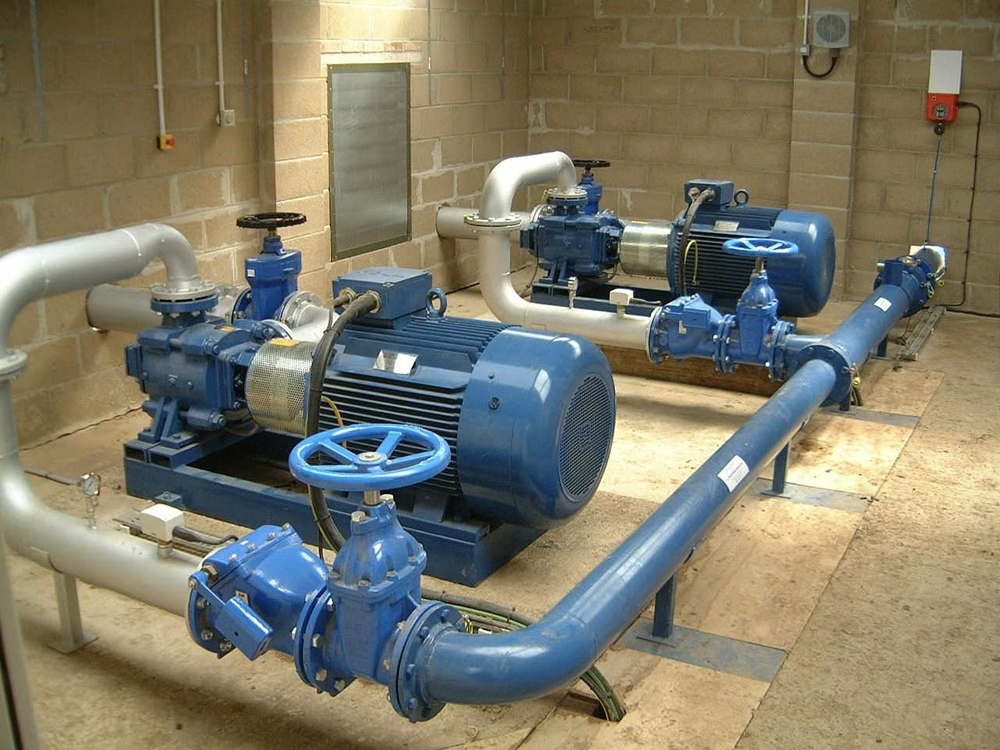
The most popular system is the cascading pump system. Let's consider a system with, for example, 2 identical pumps. The condition is that one pump is not always enough to supply water. The idea is to maintain pressure from a single pressure sensor. One option is to connect the sensor to one of the frequency converters (Master), and the other (Slave) will receive start/stop commands from the Master and rotate at the same speed. The advantage of such a system is that no external controller is needed to manage the logic. A single pressure sensor is sufficient. The reliability of the system increases because if a frequency converter fails, another one can be easily connected. Another advantage is that all frequency converters of the AC01, AC10, and AC310 series are absolutely interchangeable. That is, AC01 can synchronize with AC10 or AC310. This allows for easy replacement with another series. This system is much better than transmitting speed via analog output/input.
Let's consider the connection diagram
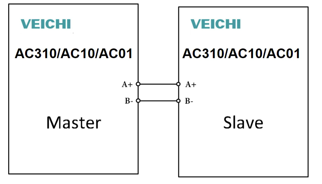
Master frequency converter parameters (Master)
F12.00 value set to 1 (Master)
F12.01 value set to 1
F12.02 value set to 3
F12.03 value set to 0
F12.10 value set to 6C31
Slave frequency converter parameters (Slave)
F01.01 value set to 2
F01.02 value set to 6
F01.07 value set to 0
F12.00 value set to 0 (Slave)
F12.01 value set to 1
F12.02 value set to 3
F12.03 value set to 0
In the Master parameters, start commands and frequency setting are chosen arbitrarily. In the Slave frequency converter, the received frequency can be corrected by combining the frequency with another source or by proportional change. There can be more than one such frequency converter in Slave mode.
All settings for this synchronization mode are found in F12 parameters.
If you are interested in this application and have questions, do not hesitate to contact us. Our engineers will help with setting up this mode.