Connecting the Frequency Converter for Adjusting the Performance of Exhaust Fan
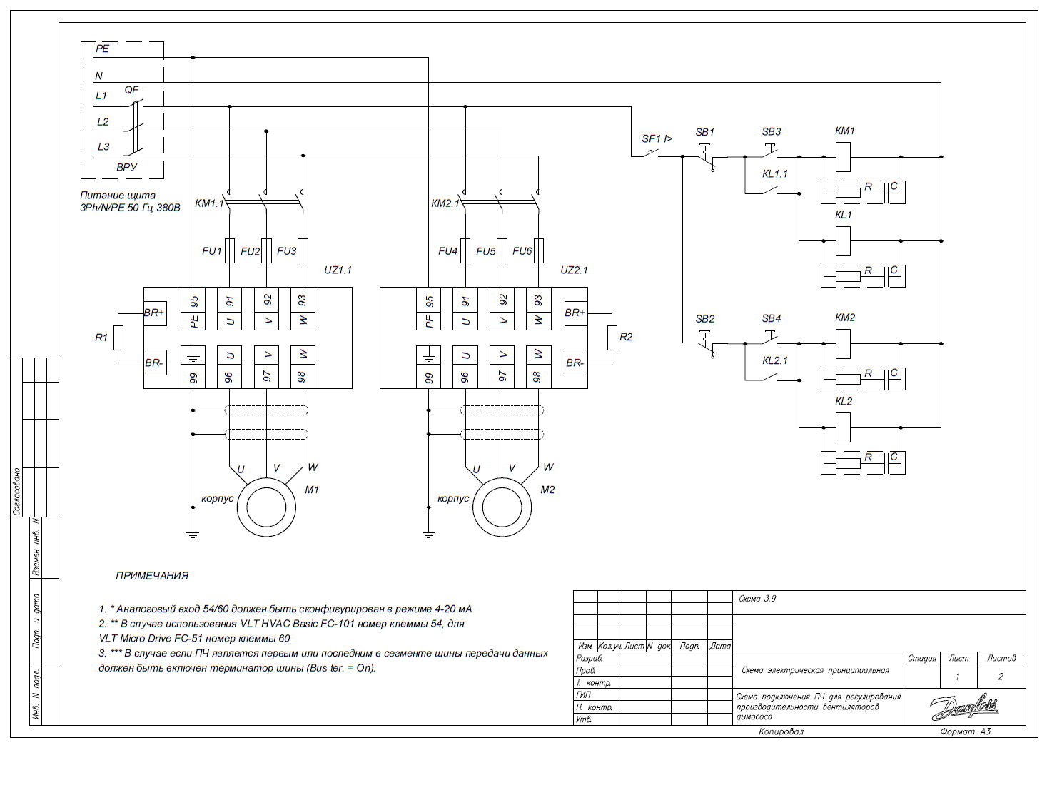
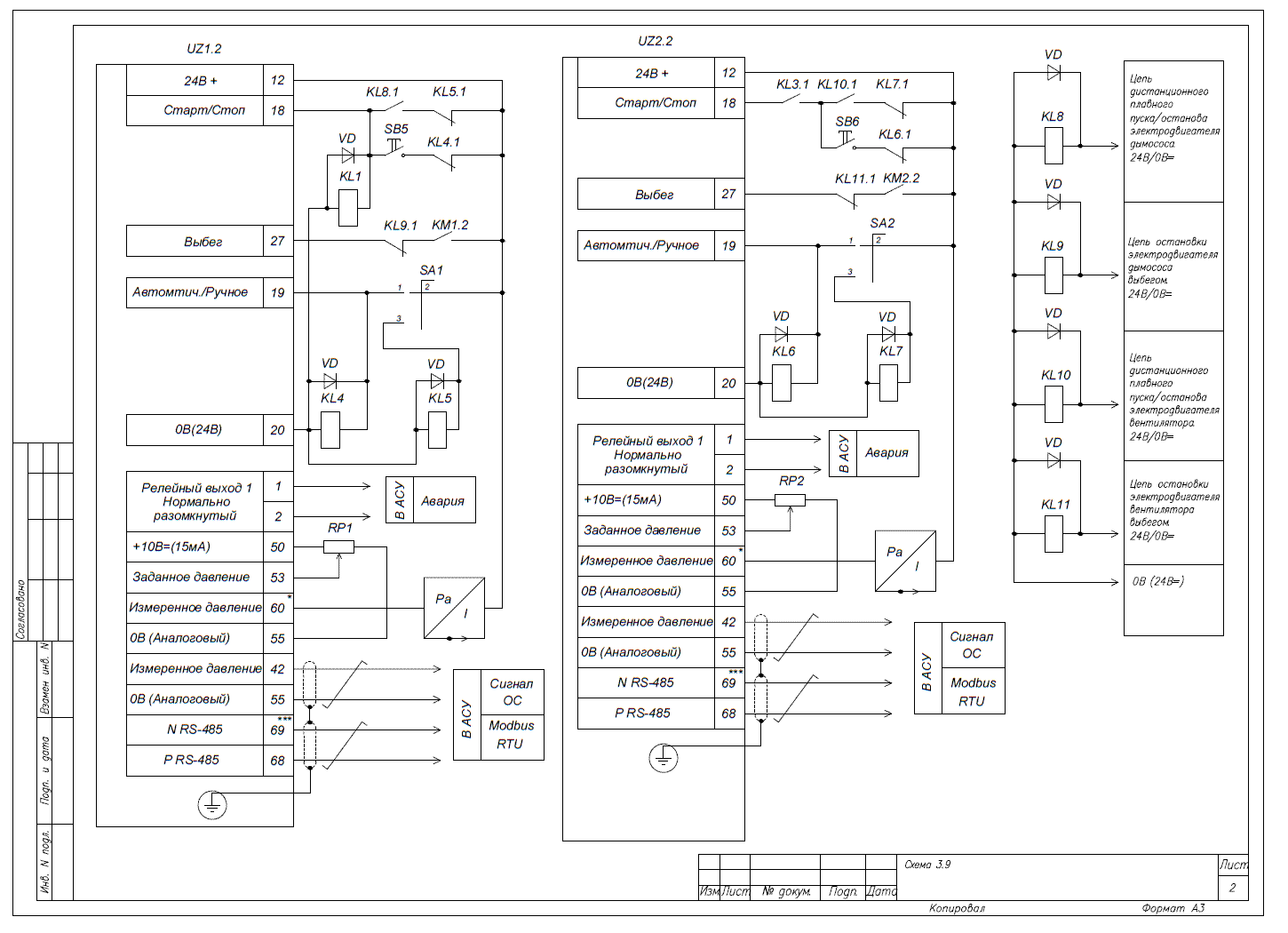
Connection diagram:


Settings for Frequency Converter Operation with Blower Fans and Exhaust Fans (for VLT Micro Drive)
Table 1: Settings for the first parameter set (automatic mode)
Parameter Code | Parameter Name | Parameter Value |
0-10 | Active Set | [9] Multi Set-up – operation with multiple parameter sets |
Perform preliminary settings as per the section "Initial Parameterization of the Frequency Converter and Basic Parameters" | ||
3-02 | Min Command | [0] min working level or min signal level from the sensor (see sensor labeling) |
3-03 | Max Command | [10] max working level or max signal level from the sensor (see sensor labeling) |
3-15 | Task Source 1 | [0] No function – no (not used, otherwise the speed command will be the sum of tasks from sources 3-10, 3-15, and 3-16) |
3-16* | Task Source 2 | [0] No function – no (not used, otherwise the speed command will be the sum of tasks from sources 3-10, 3-15, and 3-16) |
5-12* | Digital Input Function Terminal 27 | [2] – coast inverse – not used (otherwise, under factory settings, the function is coast inverse – i.e., when there is no signal from terminal 12 at terminal 27, the mechanism in coast mode (start command is ignored)) |
5-11* | Digital Input Function Terminal 19 | [23] – set up select bit 0 – parameter selection for automatic/manual modes |
6-91 | Analog Output | [12] Feedback – feedback signal |
2-10 | Braking Function | [1] Resistor brake – braking with braking resistor |
1-00* | Configuration Mode | [3] Process – PI controller mode |
7-20* | Task Source for PI Controller (for VLT Micro) | [2] Analog input 60 – analog input terminal 60 |
7-30 | Normal/Inverted Operating Mode of Controller | [0] normal (mechanism speed is higher with a + error (task – signal from the sensor)) (pressure) |
7-33* | Proportional Coefficient of the PI Controller | [1] – adjustable for application |
7-34* | Integral Coefficient of the PI Controller | [8] – adjustable for application |
3-100* | Integral Coefficient of PI Regulation | Task % from 3-03 – task support level in % from maximum value |
* Be sure to enter/check the values of these parameters
Table 2:
Settings for the second parameter set (manual mode)
Parameter Code | Parameter Name | Parameter Value |
0-10 | Active Set | [9] Multi Set-up - operation with multiple parameter sets |
Perform preliminary settings as per the section "Initial Parameterization of the Frequency Converter and Basic Parameters" (pages 50–51) | ||
3-02 | Min Command | [0] min working level or min signal level from the sensor (see sensor labeling) |
3-03 | Max Command | [10] max working level or max signal level from the sensor (see sensor labeling) |
6-91 | Analog Output | [12] Feedback – feedback signal |
2-10 | Braking Function | [1] Resistor brake – braking with braking resistor |
1-00* | Configuration Mode | [3] Process – PI controller mode |
6-12 | Terminal 53 Low Voltage | [0] – lower range of analog input 1 (lower signal level indicated on the sensor) |
6-13 | Terminal 53 High Voltage | [10] – high range of analog input 1 (upper signal level indicated on the sensor) |
6-14 | Terminal 53 Low Command | [0] – low command of analog input 1 (lower measured parameter level indicated on the sensor) |
6-15* | Terminal 53 High Command | [10] – high command of analog input 1 (upper measured parameter level indicated on the sensor) |
7-20* | Task Source for PI Controller (for VLT Micro Drive) | [2] Analog input 60 – analog input terminal 60 |
7-30 | Normal/Inverted Operating Mode of Controller | [0] normal (mechanism speed is higher with a + error (task – signal from the sensor)) (pressure) |
7-33* | Proportional Coefficient of the PI Controller | [1] – adjustable for application |
7-34* | Integral Coefficient of the PI Controller | [8] – adjustable for application |
* Be sure to enter/check the values of these parameters
