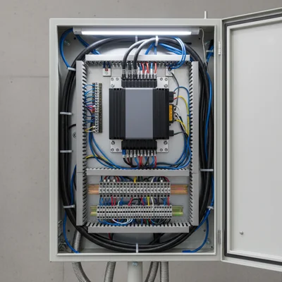
Wiring diagram of frequency converter for controlling fans in refrigeration systems
The wiring diagram of the frequency converter is used for regulating the performance of condensation fans according to the floating pressure of the refrigerant.
Wiring Diagram
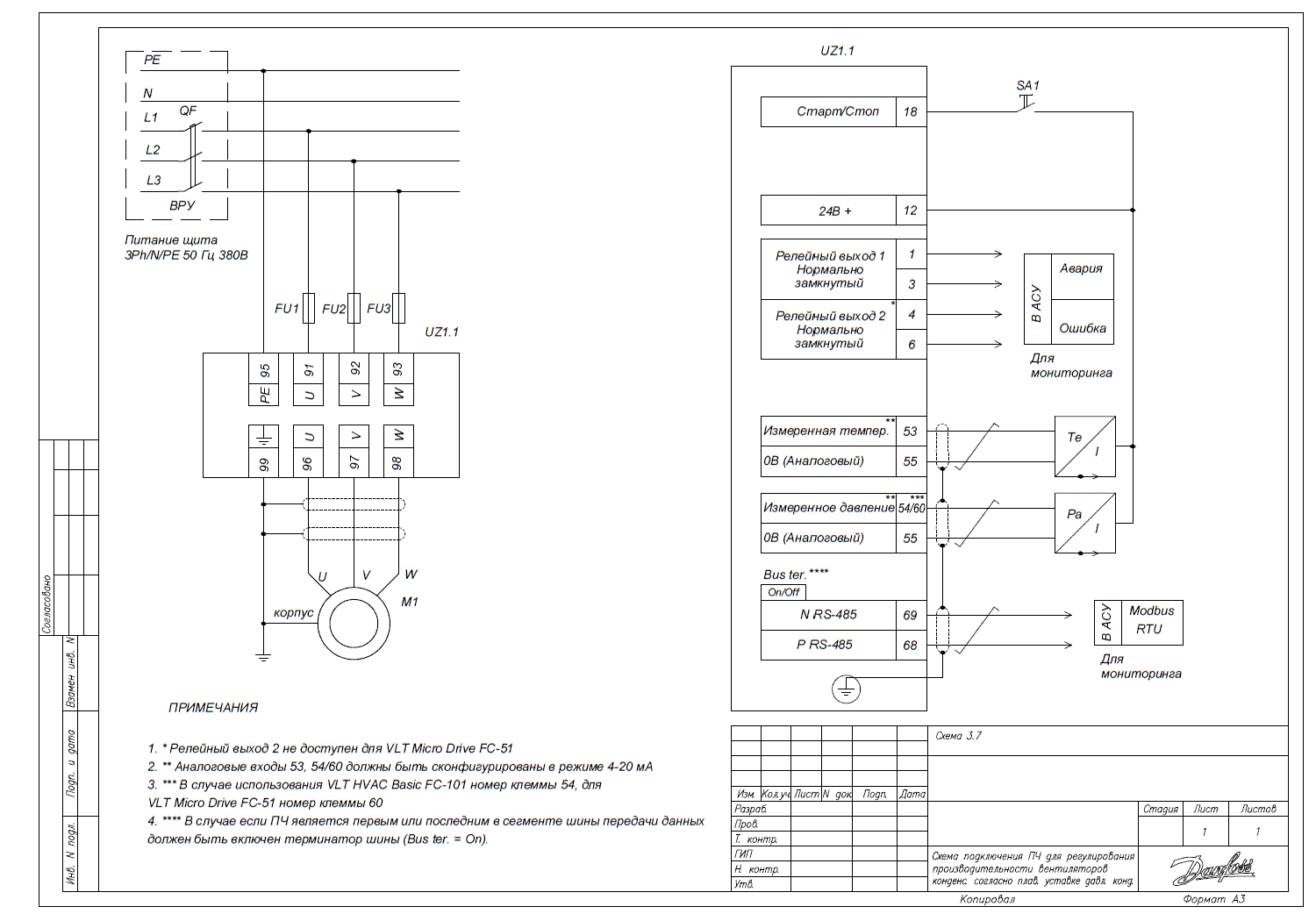
Before starting work, it is important to perform the initial setup of the converter, which includes parameters for matching with the motor, as specified in the initial configuration.
Mode for maintaining floating condensation pressure
The VLT Micro Drive FC51 is used to analyze the floating condensation pressure maintenance mode.
Sensor Data
To input information about the sensor, it is necessary to know its upper and lower temperature limits in pressure units for the selected refrigerant. It is also important to determine the correspondence between the ambient temperature and the condensation pressure.
For example, here are the sensor data for temperature in degrees Celsius:
| Temperature (°C) | -50 | -25 | 0 | 10 | 15 | 20 | 25 | 30 | 50 |
| Pcond (Bar) | 0.18 | 0.63 | 11.43 | 13.17 | 15.0 | 17.15 | 19.42 | 30.51 | 30 |
For selecting the condenser, the temperature difference ΔT = 15 °C is used. This allows determining the relationship between the ambient temperature (Tamb) and the condensation temperature (Tcond) using the formula: Tcond = Tamb + ΔT.
Each value of condensation temperature corresponds to a specific value of condensation pressure. By establishing the relationship between pressure and temperature, one can use the refrigerant table to determine the condensation pressure at a given temperature. The data is provided for refrigerant R404A; for other types of refrigerants, this calculation needs to be performed separately.
Parameter Settings
| Parameter Code | Parameter Name | Parameter Value |
| 6-12 | Class 53 Low Current | [4] mA – lower value of analog input range 1. This is the electrical signal value for the sensor as indicated in the documentation. |
| 6-13 | Class 53 High Current | [20] mA – upper value of analog input range 1. |
| 6-14 | Class 53 Low Setpoint | [0.5896] – lower setpoint of analog input 1. This parameter defines the signal from the sensor in engineering units. |
| 6-15 | Class 53 High Setpoint | [21.12] – high setpoint of analog input 1. |
| 6-22 | Class 60 Low Current | [4] mA – lower limit of analog input 2. |
| 6-23 | Class 60 High Current | [20] mA – upper limit of analog input 2. |
| 6-24 | Class 60 Low Setpoint | [0] – lower setpoint of analog input 1. |
| 6-25 | Class 60 High Setpoint | [30] – high setpoint of analog input 1. |
Note: The coefficient 0.88 is an empirical value that takes into account the nonlinearity of the relationship between condensation temperature and condensation pressure.