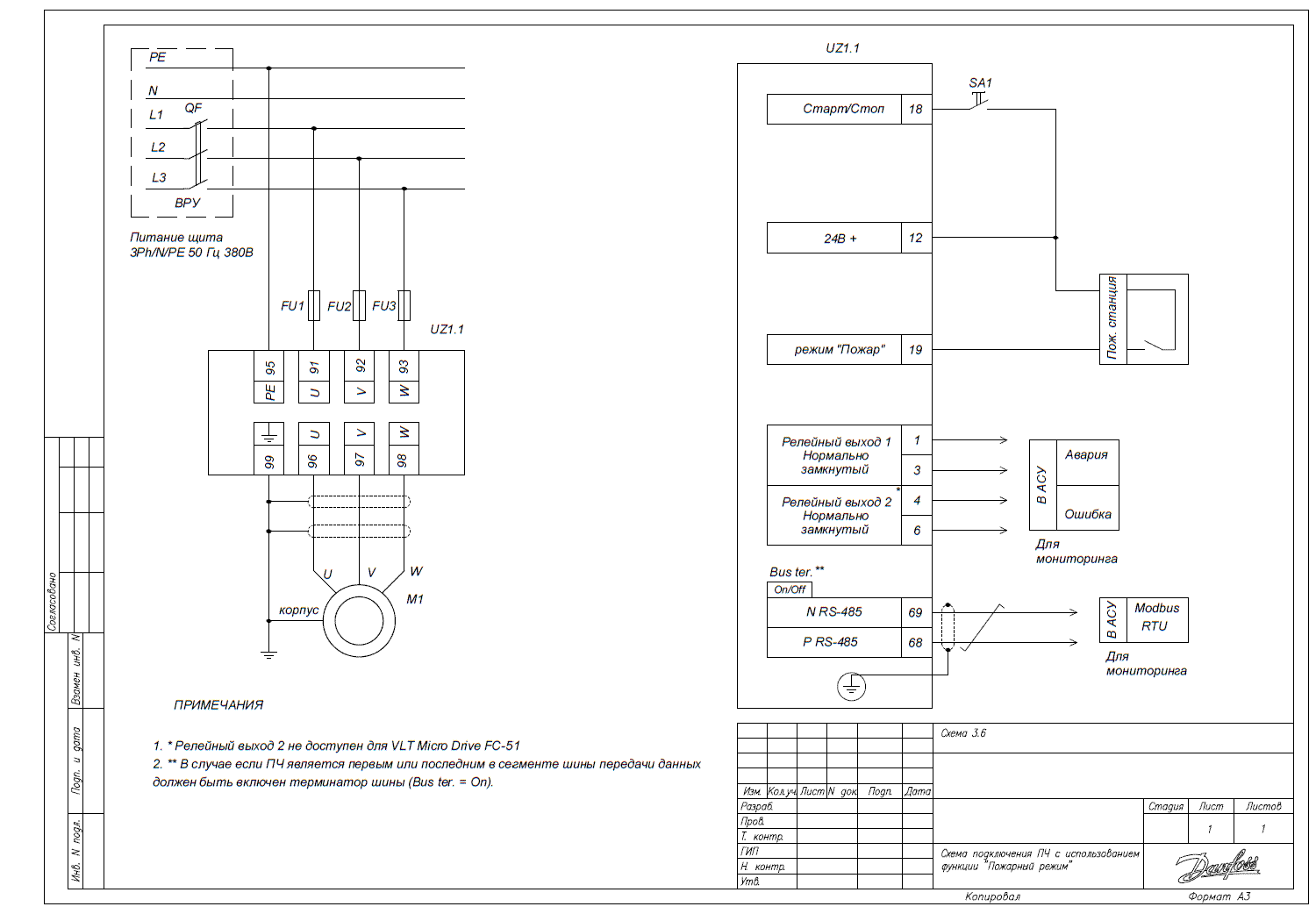
Connection of Frequency Converter with "Fire Mode" Function
In this article, we will discuss the connection of a frequency converter and the settings for the "Fire Mode" function to optimize the operation of the system.
Connection Diagram

Pre-setting the Converter
Before starting work, it is necessary to perform the pre-configuration of the converter, following the instructions for initial parameterization and adjusting the parameters according to the characteristics of the motor.
Using the Drive with Fire Mode Function (VLT HVAC Basic FC101)
For configuring the fire mode function, use the following parameters:
| Parameter Code | Parameter Name | Parameter Value |
| 3-02 | Min Setpoint | [0] minimum speed setpoint |
| 3-03 | Max Setpoint | [50] maximum speed setpoint |
| 3-15 | Source of Setpoint 1 | [0] No function – No (not used) |
| 3-16* | Source of Setpoint 2 | [0] No function – No (not used) |
| 3-100* | Fixed Speed 0 | Speed in % of 3-03 |
| 5-10 | Function of input digit 18 | [8] Start – operation of the mechanism in accordance with the setpoint in the presence of a 24V signal (terminal 12) at terminal 18. A switch is installed between terminals 12 and 18, upon closing which the mechanism operates (the converter must be in Auto On mode). |
| 5-11 | Function of input digit 19 for VLT HVAC Basic | [37] Fire mode – fire mode (the converter operates until the last, ensuring the fan's operation). |
| 5-12* | Function of digital input terminal 27 for VLT HVAC Basic | [0] No function – not used (otherwise, by factory settings, the inverse run function – in the absence of a signal from terminal 12, the mechanism is in the runaway state, the start command is ignored). |
| 5-400 | Relay Function 1 | [2] Drive Ready – the drive is ready for operation/in operation. |
| Relay Function 2 (available on VLT HVAC Basic) | [9] Alarm – emergency (red light), the converter is in an emergency state. |
* Be sure to enter/check the values of these parameters, as they may differ from the factory settings.