Connecting frequency converters with fan synchronization via analog signal
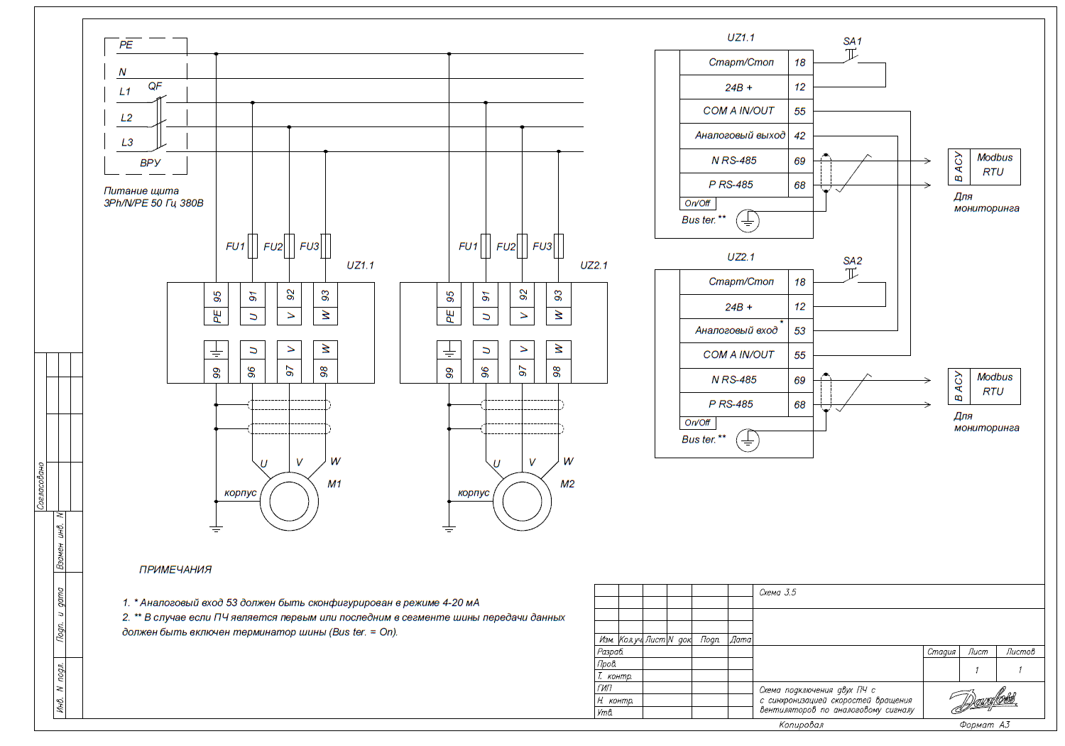
This article describes how to connect two frequency converters to achieve synchronous operation of fans using an analog signal.
Wiring diagram

Synchronous rotation speed of drives
At the beginning of using each converter, it is necessary to set basic parameters agreed with the corresponding motor.
Below are the settings for the leading and lagging converters to establish synchronous operation of the two fans.
Converter settings on the leading drive
| Parameter code | Parameter name | Parameter value |
| 3-02 | Min setpoint | [0] minimum speed setpoint |
| 3-03 | Max setpoint | [50] maximum speed setpoint |
| 3-15 | Setpoint source 1 | [0] No function – not used |
| 3-16* | Setpoint source 2 | [0] No function – not used |
| 5-10 | Function of digital input 18 | [8] Start – operation of the mechanism according to the setpoint with a 24V signal (terminal 12) on terminal 18. A switch is installed between terminals 12 and 18, when closed, the mechanism operates (the VFD must be in Auto On mode). |
| 5-12* | Function of digital input terminal 27 for VLT HVAC Basic | [0] – No function – not used. Otherwise, according to factory settings, the run function is inverse, i.e., when there is no signal on terminal 27, the mechanism is in run, the start command is ignored. |
| 3-10 | The converter transmits information about speed on the analog output | - |
* The values of some parameters may differ from factory settings, they should be checked and set according to the specific wiring diagram.
Converter settings on the lagging drive
| Parameter code | Parameter name | Parameter value |
| 3-02 | Min setpoint | [0] minimum speed setpoint |
| 3-03 | Max setpoint | [50] maximum speed setpoint |
| 3-15 | Setpoint source 1 | [0] No function – not used |
| 3-16* | Setpoint source 2 | [0] No function – not used |
| 5-10 | Function of digital input 18 | [8] Start – operation of the mechanism with a signal of 24V on terminal 18. |
| 5-12* | Function of digital input terminal 27 for VLT HVAC Basic | [0] – No function – not used. |
| 6-19* | Terminal 53, mode | [1] Current mode – current mode of analog input 1. |
| 6-12* | Fixed speed 0 | [4] mA – low current level. |
| 6-01 | Function during timeout of input 53 | [2] Stop – stop the drive during a break. |
| 6-91 | Terminal 42, analog output | [10] output frequency – output frequency. |
| 6-14 | Terminal 53 high setpoint | [50] – high setpoint of analog input 1. |
* The values of some parameters may differ from factory settings, they should be checked and set according to the specific wiring diagram.
