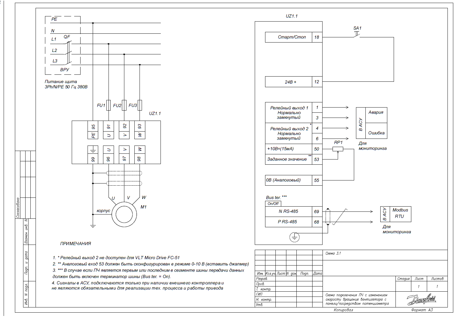
Connecting the frequency converter with speed adjustment based on the analog sensor signal
Before setting up the connection scheme of the drive through the frequency converter for control using a signal from an analog sensor, it is essential to perform the initial setup of the key parameters of the frequency converter. In this article, we will examine two examples of configuring the VFD parameters for typical situations.
Constant pressure maintenance mode based on the analog sensor signal

Below is a table with parameters for configuration:
| Parameter code | Parameter name | Control parameter values using discrete signals from the controller |
| 3-02 | Min setpoint | [0] minimum operating level or minimum signal level from the sensor (see sensor labeling) |
| 3-03 | Max setpoint | [10] maximum operating level or maximum signal level from the sensor (see sensor labeling) |
| 3-15 | Source of setpoint 1 | [0] No function – no (not used, otherwise the speed setpoint will be the sum of inputs from sources 3-10, 3-15, and 3-16) |
| 3-16* | Source of setpoint 2 | [0] No function – no (not used, otherwise the speed setpoint will be the sum of inputs from sources 3-10, 3-15, and 3-16) |
| 4-12 | Minimum rotation speed | [0] Hz – for most fan applications [20] Hz – for pumps (to prevent overheating and wear of mechanisms), to ensure minimum air exchange |
| 6-12 | Terminal 53 low current | [4] mA – lower range of analog input 1 (lower signal level specified on the sensor) |
| 6-13 | Terminal 53 high current | [20] mA – upper range of analog input 1 (upper signal level specified on the sensor) |
| 20-00* | PI controller OS source (for VLT HVAC Basic) | [1] Analog input 53 – analog input 1 terminal 53 |
| 20-93* | Proportional coefficient of PI controller (for VLT HVAC Basic) | [8] – set for application |
| 3-100* | Setpoint | Setpoint in percentage of parameter 3-03 – level setpoint in percentage of maximum value |
* The values of some parameters may differ from factory settings. They should be checked and set according to the specific connection scheme.
Setting the PI controller coefficients for constant pressure mode
- Set 7-34 = 9999, 7-33 = 0.3. Gradually increase the value of 7-33 until oscillations occur.
- Reduce the value of parameter 7-33 by 40% and fix it.
- At the found value of 7-33, set parameter 7-34 = 20 and decrease until oscillations or excessive overshoot occur.
- Increase the value of 7-34 by 25% and fix it.
Setting the VLT Micro Drive FC51 frequency converter for controlling the refrigeration compressor
The table below contains parameters for configuration:
| Parameter code | Parameter name | Control parameter values using discrete signals from the controller |
| 3-02 | Min setpoint | [0] minimum operating level or minimum signal level from the sensor (see sensor labeling) |
| 3-03 | Max setpoint | [10] maximum operating level or maximum signal level from the sensor (see sensor labeling) |
| 4-12 | Minimum possible speed limit | [35] Hz – Minimum possible speed |
| 4-14 | Maximum possible speed limit | [50] Hz – Maximum possible speed |
| 5-40 | Controller operating mode | [1] inverse (compressor) |
| 7-33* | Proportional coefficient of the PI controller | [1] – set for application |
| 7-34* | Integral coefficient of the PI controller | [8] – set for application |
| 3-100* | Setpoint | Setpoint in % of 3-03 – level support setpoint in % of maximum value |
* Be sure to check the specified parameter values, as they may differ from factory settings.
Setting the PI controller coefficients
- Set parameter 7-34 = 9999, 7-33 = 0.3. Gradually increase the value of 7-33 until oscillations occur.
- Reduce the value of parameter 7-33 by 40% and fix it.
- At the found value of 7-33, set 7-34 = 20 and decrease until oscillations or excessive overshoot occur.
- Increase the value of 7-34 by 25% and fix it.
