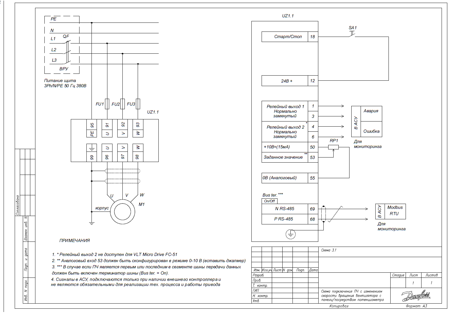
Connecting the frequency converter for speed control using discrete signals from the controller
Wiring diagram

Before configuring the drive connection scheme through the frequency converter for regulation using discrete signals from the controller, preliminary setting of the basic parameters of the converter must be performed. Then, the following parameters need to be set in the converter menu:
| Parameter Code | Parameter Name | Parameter Value for Control Through Discrete Signals from the Controller |
| 3-02 | Minimum Setpoint | "0" minimum speed setpoint |
| 3-03 | Maximum Setpoint | "50" maximum speed setpoint |
| 3-15 | Setpoint Source 1 | "0" No function – not used. Otherwise, the speed setpoint will be the sum of the setpoints from sources 3-10, 3-15, and 3-16. |
| 3-16* | Setpoint Source 2 | "0" No function – not used. Otherwise, the speed setpoint will be the sum of the setpoints from sources 3-10, 3-15, and 3-16. |
| 5-12* | Function of Digital Input Terminal 27 for VLT HVAC Basic | |
| 5-400 | Relay Function 1 | "2" Drive Ready – the drive is ready for operation. |
| 5-401 | Relay Function 2 | "9" Alarm – fault. The converter is in a fault state. |
Further adjustments depend on the number of rotation speeds of the shaft that are intended to be used. For operation at one speed, use switch T1 (closed) and set the parameters:
| Parameter Code | Parameter Name | Parameter Value |
| 5-10 | Function of Digital Input Terminal 18 | "8" – Start – the mechanism rotates according to the speed setpoint when a 24V signal is present. |
| 3-100* | Fixed Speed 0 | Speed in % of 3–03 |
When setting two speeds, switches T1 and T2 should be used, and the following parameters should additionally be set:
| Parameter Code | Parameter Name | Parameter Value |
| 5-13 | Function of Input Digits 29 | "16" Preset ref bit 0 – setpoint set bit 0. |
| 5-15 | Function of Input Digits 33 | "0" – no function – not used. |
| 3-101* | Fixed Speed 1 | Speed 1 in percentage of parameter value 3–03. Switch T1 must be on at this time. |
When setting three or four speeds, switches T1, T2, and T3 should be used, and additionally set:
| Parameter Code | Parameter Name | Parameter Value |
| 5-11* | Function of Digital Input 19 | "17" Preset ref bit 1 – bit 1 for speed selection. |
| 3-102* | Fixed Speed 2 | Speed 2 in percentage of parameter value 3-03. Switch T1 must be on at this time. |
| 3-103 | Fixed Speed 3 | Speed 3 in percentage of parameter value 3-03. Switch T1 must be on at this time. |
When setting up to eight speeds, switches T1, T2, T3, T4 should be used, with additional settings:
| Parameter Code | Parameter Name | Parameter Value |
| 5-12* | Function of Digits Input 27 | "18" Preset ref bit 2 – bit 2 for speed selection. |
| 3-104* | Fixed Speed 4 | Speed 4 in percentage of parameter value 3-03. |
| 3-105 | Fixed Speed 5 | Speed 5 in percentage of parameter value 3-03. |
| 3-106 | Fixed Speed 6 | Speed 6 in percentage of parameter value 3-03. |
| 3-107 | Fixed Speed 7 | Speed 7 in percentage of parameter value 3-03. |
* Some parameters may differ from the factory settings; they should be checked and set according to the specific wiring scheme.
Table of Positions for Switches T1, T2, T3, and T4 for Selecting Necessary Speeds
| Switches | T1 Start | T2 Bit 0 | T3 Bit 1 | T4 Bit 2 |
| Speeds | ||||
| Stop | OFF | any | any | any |
| 3-10 | ON | OFF | OFF | OFF |
| 3-101 Speed 1 | ON | OFF | OFF | ON |
| 3-102 Speed 2 | ON | OFF | ON | OFF |
| 3-103 Speed 3 | ON | OFF | ON | ON |
| 3-104 Speed 4 | ON | ON | OFF | OFF |
| 3-105 Speed 5 | ON | ON | OFF | ON |
| 3-106 Speed 6 | ON | ON | ON | OFF |
| 3-107 Speed 7 | ON | ON | ON | ON |