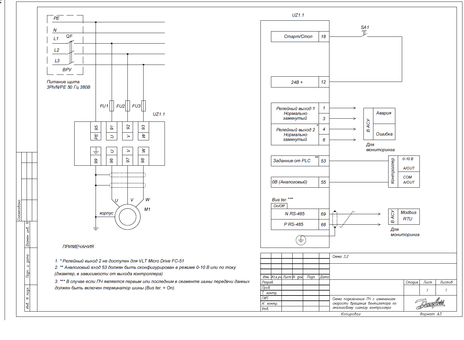
Connection of the frequency converter for fan speed control
To implement the rotation speed control of the three-phase asynchronous motor shaft using the analog signal from the controller, it is necessary to pre-configure the frequency converter, taking into account the specific features of the motor model.
Connection diagram

Frequency converter configuration parameters
It is important to enter the following settings through the frequency converter menu:
Parameter Code | Parameter Name | Parameter Value |
3-02 | Minimum Setpoint | "0" – minimum speed setpoint |
3-03 | Maximum Setpoint | "50" – maximum speed setpoint |
3-15 | Setpoint Source 1 | "1" – Analog in 53 (signal from the controller) |
3-16 | Setpoint Source 2 | "0" – No function – not used |
5-10 | Function of digital input 18 | "8" – Start – operation of the mechanism with a 24V signal on terminal 18 |
6-10 | Terminal 53 low voltage | "0" – V/mA – lower limit of the analog input range 1 |
5-12* | Function of digital input terminal 27 for the VLT HVAC Basic model | "0" – No function – not used |
5-400 | Relay Function 1 | "2" – Drive Ready – drive is ready for operation |
5-401 | Relay Function 2 (available for the VLT HVAC Basic model) | "9" – Alarm – fault (red light) |
8-30 | Protocol | "2" – ModBus RTU – communication between the controller and the frequency converter |
8-31 | Address of the converter in the network | "2" – address of the frequency converter in the network |
8-32 | Communication speed for the protocol | "2" – 9600 bps – connection speed for the protocol |
* The values of some parameters may differ from factory settings; they should be checked and set according to the specific connection scheme.