Connecting the frequency converter for pump control in tanks
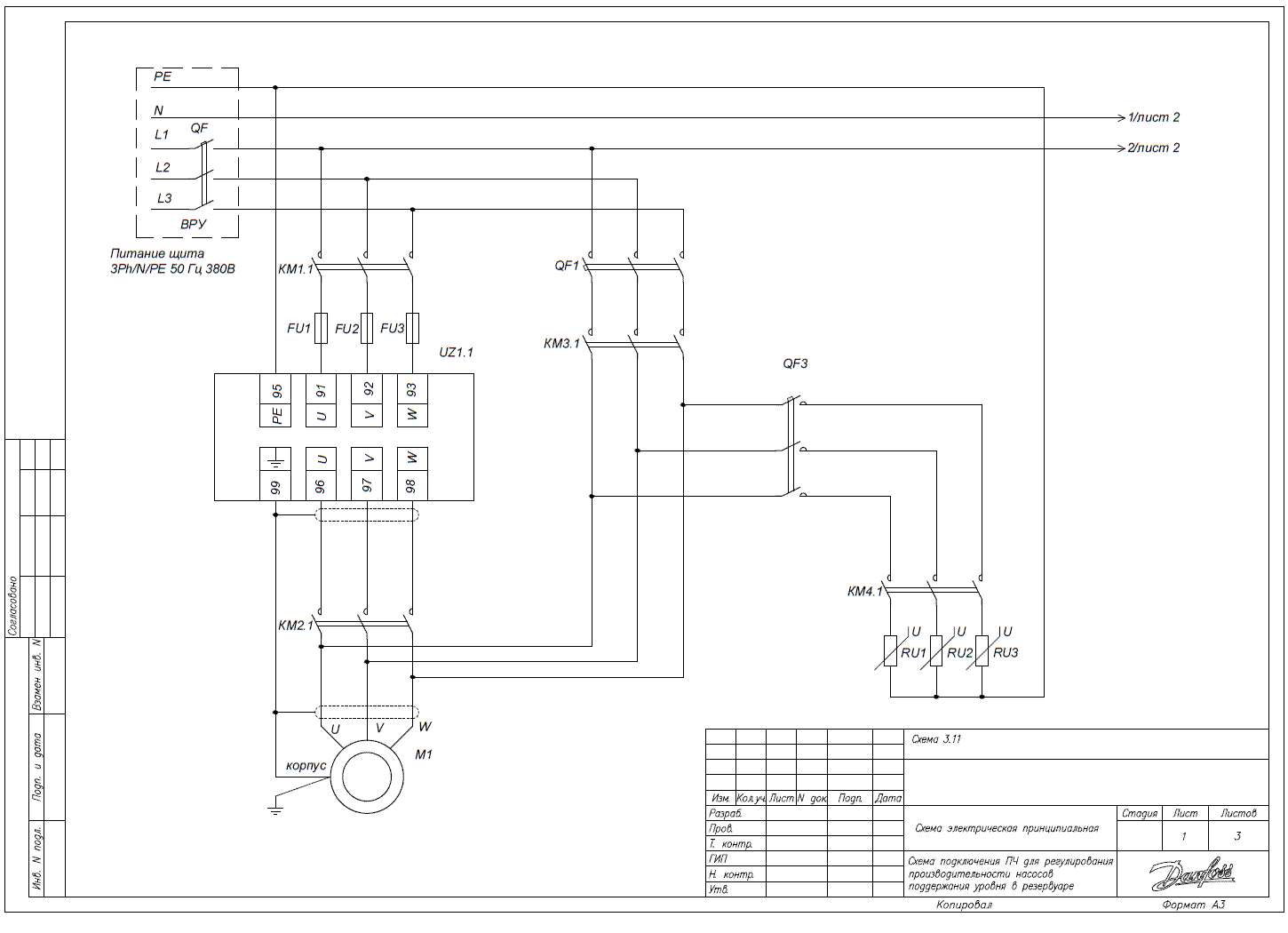
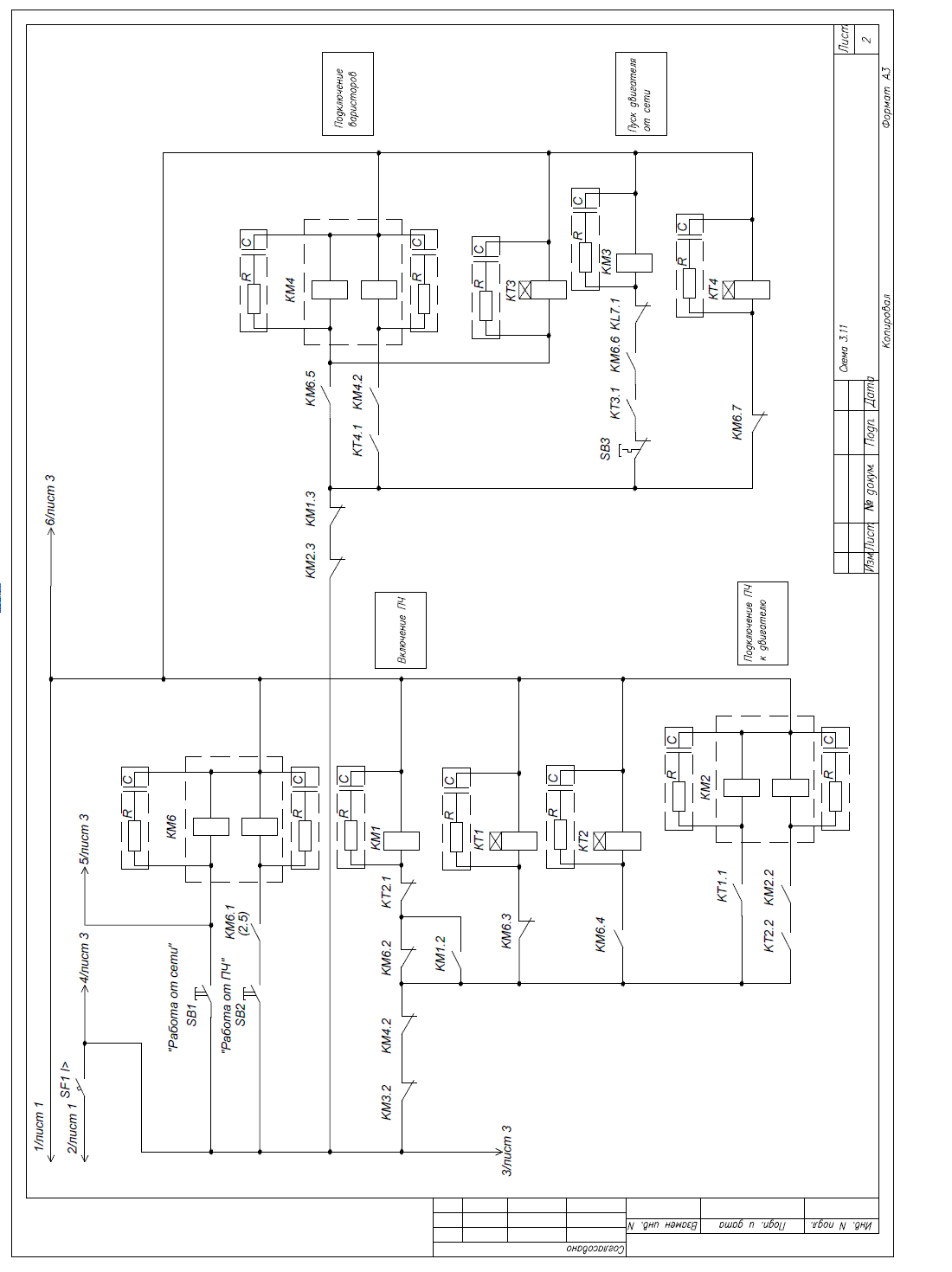
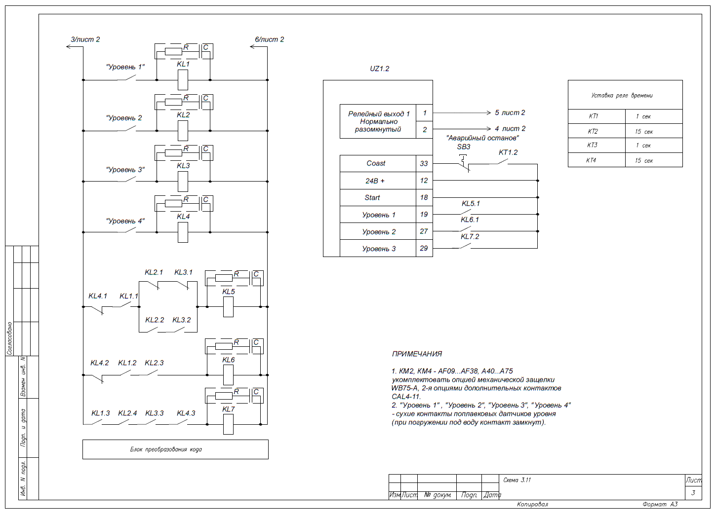
The wiring diagram for connecting the frequency converter for regulating the performance of pumps in a tank is presented below:


Controlling the pump rotation speed
For effective control of the pump rotation speed, which operates with a storage capacity, it is necessary to perform the initial setup of the frequency converter according to the basic parameters.
Main regulation parameters
Parameters for connecting the frequency converter:
Parameter Code | Parameter Name | Parameter Value |
3-02 | Min Setpoint | [0] minimum rotation frequency setpoint |
3-03 | Max Setpoint | [50] maximum rotation frequency setpoint |
3-15 | Setpoint Source 1 | [0] No function – not used (otherwise, the speed setpoint will be the sum of setpoints from sources 3-10, 3-15, and 3-16) |
3-16* | Setpoint Source 2 | [0] No function – not used (otherwise, the speed setpoint will be the sum of setpoints from sources 3-10, 3-15, and 3-16) |
5-10 | Digital Input Function (terminal 18) | [8] – Start – command to start (terminal 18) |
5-15* | Digital Input Function (terminal 33) | [2] – Coast inverse – inverse coast (start command is ignored with no signal at terminal 27) |
5-400 | Relay Function 1 | [2] Drive Ready – drive is ready for operation (green light indicates power supply to the converter) |
5-12 | Input Function 27 | [17] Preset ref bit 1 – setpoint bit 1 (speed selection when T2 and T1 are closed) |
5-13* | Input Function 29 | [18] Preset ref bit 2 – bit 2 for speed selection |
5-11* | Input Function 19 | [16] Preset ref bit 0 – bit 0 for speed selection |
3-101* | Fixed Speed 1 | [0] Speed in % of 3-03 – stop upon activation of sensor 1 |
3-102* | Fixed Speed 2 | [60] Speed in % of 3-03 – optimal speed for activating sensor 2 |
3-103 | Fixed Speed 3 | [90] Speed in % of 3-03 – fast ramp speed when sensor 3 is activated |
3-104 | Fixed Speed 4 | [100] Speed in % of 3-03 – maximum speed for activating sensor 4 |
* Make sure to enter/check the values of these parameters, as they may differ from factory settings.
