Connecting a Frequency Converter for Fan Speed Control
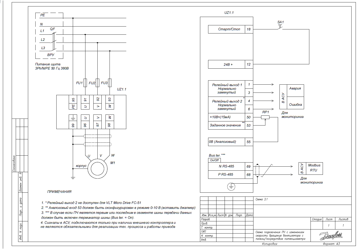
This article is dedicated to the connection of a frequency converter that allows adjusting the speed of fans using a control panel or potentiometer.
Connection Diagram

Initial Configuration
To adjust the rotation speed of the shaft of a three-phase asynchronous motor using a potentiometer, it is necessary to perform the initial configuration of the frequency converter taking into account the specific model of the motor.
Setting Required Parameters
It is also necessary to set the following parameters through the frequency converter menu:
Parameter Code | Parameter Name | Parameter Value for Adjustment with External Potentiometer |
3-02 | Minimum Setting | "0" - minimum speed setting |
3-03 | Maximum Setting | "50" - maximum speed setting |
3-15 | Task Source 1 | "1" Analog in 53 – analog input 1 (potentiometer) will perform the function of the speed command source |
3-16 | Task Source 2 | "0" No function – additional speed command source is not used. (If used, the sum of sources 3-15 and 3-16 will act) |
5-10 | Function of Digital Input 18 | "8" Start – the motor shaft will rotate according to the command if there is a voltage of 24V between terminals 12 and 18 (a switch should be installed between these terminals, and the converter should be in "Auto On" mode). |
6-10 | Terminal 53 Low Voltage | "0" Minimum voltage – lower limit of the range of values for analog input 1 (for standard potentiometers, the range is 0-10 V). |
6-11 | Term | |
6-14 | Terminal 53 Low Setting | "0" – low setting of analog input 1 (the speed of the mechanism which corresponds to the minimum voltage from the potentiometer, if the potentiometer's knob is turned to the left (6-10 = 0 V), the mechanism should rotate at a frequency of 6-14 = 0 Hz). |
6-15 | Terminal 53 High Setting | "50" – high setting of analog input 1 (the speed of the mechanism, which corresponds to the maximum voltage from the potentiometer, if the potentiometer's knob is turned to the right (6-11 = 10 V), the mechanism should rotate at a frequency of 6-14 = 50 Hz). |
5-12 | Function of Digital Input for VLT HVAC Basic Model | "0" – No function – not used. (Otherwise, by factory settings, the coast function is inverse – that is, when there is no signal from terminal 12 on terminal 27, the mechanism is in coast, and the start command is ignored.) |
5-400 | Relay Function 1 | "2" Drive Ready – the drive is ready for operation. A green light indicates that the frequency converter is powered and ready to operate. |
5-401 | Relay Function 2 (relay available on VLT HVAC Basic model) | "9" Alarm – fault (red light). The frequency converter is in a fault state. |
