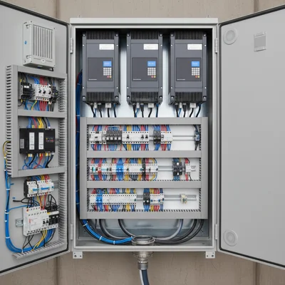
Installation and Programming of the Frequency Converter
Turning on and configuring the frequency converter program requires more actions than simply connecting cables according to the diagram. A separate task is creating the configuration for the frequency inputs in 2017.
Frequency Inputs
Discrete inputs can be in two forms: connected and disconnected. Using external disconnectors allows for a variety of functions. Specific values are assigned to separate buttons, such as speed, reverse, and start. These capabilities are programmable for all converters.
- Simple signals can have values from 0 to 10 volts or 4-20 milliamperes.
- Inputs are divided into connected and separate.
- Changing the potential at the input leads to a change in the converter's output frequency.
Frequency Outputs
Discrete outputs are characterized by two positions and can be of two types: dry contact and open collector. Outputs can be used for:
- Controlling pumps;
- Power switching;
- Alerting.
Creating Frequency Converter Programs
In 2017, new software tools are used for creating frequency converter programs, enabling the programmer to quickly identify errors, make changes, and correct actions. Messages during programming appear on the screen, making this option accessible for many converters.
Many frequency converter manufacturers aim for the programming of equipment to be carried out by qualified specialists who consider the operating conditions of the mechanisms, as well as the requirements of the customers.
Adjusting the Mechanism
The adjustment process includes defining the following values:
- Source of control commands;
- Frequency setpoint command from the source.
Other parameters are described in detail in the documentation for the frequency converter.
- Stop (STOP)
- Forward (FWD)
- Reverse (REV)
The control data from sources are defined by value (201):
- 201 = 0 – Frequency converter control panel (default)
- 201 = 1 – External signals with the possibility of using the "STOP" button
- 201 = 2 – External signals prohibit the "STOP" button
- 201 = 3 – Program type transmitting RS-485 allows the "STOP" button
- 201 = 4 – Program type transmitting RS-485 prohibits the "STOP" button
In many converters, command sources can be switched using a programmable discrete input. For example, in the VFD-VE series, the command control source is changed using the PU button, and in the VFD-C2000 series – the HAND button on the control panel.
For initial setup, the main source of control command messages must be defined. If it is the built-in control panel, then the setup is complete.
Connecting Control Signals
For connecting external signals, there are two options: active or inactive "STOP" button on the panel. The working signal position is Ground. Activation of the command occurs when Ground is connected to the discrete input. These are contacts connected to switches, relays, or standard buttons.
It is important that the level of activity of the control signal can be set at the positive terminal of the motor power supply. The location of the microswitch can be found in the documentation for the converter. Many converters have a built-in voltage source for controlling input commands.
All connections can only be made with the motor turned off and power supply at 220V. Detailed connection diagrams can be found in the equipment documentation.
Setting the Frequency Setpoint Source
The command to determine the frequency can come from various sources. The choice of source is defined by parameters Pr 02-00 (output frequency determination source) or Pr 00-20. The size of the parameter may differ in different series.
Frequency setpoints can be supplied from:
- Control panel keys;
- External terminals;
- From a potentiometer on the panel;
- Frequency pulse;
- RS-485 interface;
- CAN open commands.
Programming Frequency Converter Parameter Values
After pressing the PROG (ENTER) button, a group of parameters is displayed. The up and down buttons change the group to the desired one. Pressing the PROG button opens the parameter number value. After making changes, we save the selected value.
After completing the frequency converter setup, it is recommended to refer to the technical documentation, which answers many questions.
Procedure for the First Start of the Frequency Converter
- Check for matching voltage values of the network and motor;
- Control connection to the network and motor;
- Start the first turn-on, reset parameter values;
- Set the source of control commands;
- Program the frequency setpoint;
- Various settings.