VFD Working Principle: From Theory to Practice
A variable frequency drive (VFD, also known as a frequency converter, inverter, or AC drive) is a power electronic device that modifies the frequency and amplitude of the supply voltage feeding an electric motor. This gives the operator full control over shaft speed, torque output, and acceleration profile. Across industrial facilities in Ukraine — from water-pumping stations in Kyiv to conveyor lines in Dnipro — VFDs save enterprises between 30% and 60% of their electricity costs every single day.
The frequency converter catalogue at chastotnik.ua features over 1,300 models from Schneider Electric, Siemens, ABB, Danfoss, INVT, Veichi, and other manufacturers, with power ratings from 0.4 kW to 500 kW. Below we examine exactly how a VFD works, what functional blocks it contains, and why the investment in a variable frequency drive typically pays for itself within 6 to 18 months.
Internal Structure of a Variable Frequency Drive: Three Key Blocks
Every modern VFD consists of three functional stages that process the electrical signal in sequence:
1. Rectifier
The first stage converts the AC mains voltage (220 V or 380 V, 50 Hz) into direct current. Budget models use an uncontrolled diode bridge, while more advanced units employ a controlled thyristor or IGBT rectifier with an active front end (AFE). A diode bridge is simpler and more reliable; a thyristor-based design can regenerate braking energy back into the supply network.
2. DC Bus (Intermediate DC Link)
Between the rectifier and the inverter there is a capacitor filter bank. Its purpose is to smooth the pulsations of the rectified voltage and create a stable DC source. The DC bus voltage is typically 540 V for a three-phase 380 V supply or 310 V for single-phase 220 V. This stage may also include a braking resistor or braking chopper when the motor undergoes frequent stops — for example in lifts, cranes, or centrifuges.
3. Inverter (Power Module)
The final block consists of six IGBT transistors (for three-phase output) that switch the DC bus voltage according to a pulse-width modulation (PWM) algorithm. A microcontroller governs the switching sequence and duration so that the output forms a three-phase voltage at the required frequency — anywhere from 0 Hz to 400 Hz and above. The PWM carrier frequency typically ranges from 2 to 16 kHz. A higher carrier frequency reduces audible motor noise but increases transistor switching losses.
How a VFD Controls Motor Speed: V/f Law and Vector Control
The rotational speed of an asynchronous motor is directly proportional to the supply frequency, described by the formula:
n = 120 × f / p
where n is revolutions per minute, f is frequency (Hz), and p is the number of motor poles. For a typical 4-pole motor the synchronous speed is 1,500 rpm at 50 Hz, 750 rpm at 25 Hz, and 2,250 rpm at 75 Hz.
Scalar Control (V/f or U/f)
The simplest mode: the VFD changes frequency and voltage proportionally, maintaining a constant V/f ratio. This is suitable for pumps, fans, and simple conveyors where high torque at low speeds is not required. Most models in our catalogue support scalar control by default.
Vector Control (FOC / SVC)
The drive's microprocessor decomposes motor current into two components — a magnetising component and a torque-producing component — and controls them independently. This delivers 100% rated torque even at 0.5 Hz (approximately 15 rpm), speed accuracy of ±0.5% without an encoder and ±0.01% with one. Vector control is essential for cranes, lifts, extruders, and CNC machines. For example, the INVT GD20 series and the Veichi AC70 both support sensorless vector control as standard.
Comparison: Direct-On-Line Start vs Soft Starter vs VFD
| Parameter | Direct-On-Line (DOL) | Soft Starter | Variable Frequency Drive (VFD) |
|---|---|---|---|
| Starting current | 600–800% of rated | 200–350% of rated | 100–150% of rated |
| Mechanical shock at start | Maximum | Reduced | None |
| Speed regulation | Not possible | During start/stop only | Smooth 0–100% and above |
| Energy savings | 0% | 5–15% (start phase only) | 30–60% for fan/pump loads |
| Motor protection | Circuit breaker | Basic (current, overheating) | Comprehensive (current, voltage, overheating, phase loss, earth fault) |
| Energy regeneration | No | No | Yes (with AFE module) |
| Cost | Lowest | Medium | Highest (but pays for itself) |
| Payback period | — | 2–4 years | 6–18 months |
The comparison clearly shows that a soft starter addresses inrush-current problems but does not deliver energy savings during normal operation. A VFD provides both advantages simultaneously. For a more detailed discussion of the differences, read our article Top Questions About Frequency Drives and Soft Starters.
7 Reasons Why a Variable Frequency Drive Pays for Itself
1. Electricity Cost Reduction of 30–60%
The affinity laws state that the power consumed by a pump or fan is proportional to the cube of the speed. Reducing speed by just 20% yields a 50% energy saving. In practice, a pumping station with a 7.5 kW motor running 8,000 hours per year saves approximately 15,000–20,000 kWh annually with a VFD. At a tariff of 3 UAH/kWh, that translates to 45,000–60,000 UAH per year.
2. Smooth Start-Up Without Mechanical Shocks
A VFD accelerates the motor over a programmable ramp time (typically 5–30 seconds) with a linear or S-curve acceleration profile. This eliminates water hammer in pipelines, jerking of belt conveyors, and belt slippage. The result is significantly less wear on couplings, bearings, and gearboxes.
3. Comprehensive Motor Protection
A modern VFD monitors over 30 parameters in real time: current in each phase, DC bus voltage, heatsink and motor temperature (via PTC/KTY sensor), insulation resistance, phase loss, earth fault, overload, and underload (dry-run pump protection). This is far more reliable than a conventional thermal relay and circuit breaker.
4. Motor Lifespan Extended by a Factor of 2–3
Without a VFD, every direct start subjects the windings to thermal stress (inrush current of 6–8×In heats the copper). After 10,000 starts the insulation degrades noticeably. With a VFD the starting current does not exceed 1.5×In, extending winding life several-fold. Additionally, running at reduced speed lowers vibration and bearing wear.
5. Precise Process Control
A VFD with a built-in PID controller maintains a setpoint for pressure, temperature, or level to within 1–2% accuracy. For example, in a water-supply system the drive automatically speeds up the pump when demand increases and slows it down when demand drops, maintaining a steady 3.5 bar across the entire load range. For more on using VFDs in ventilation systems, read our article on frequency converters for ventilation.
6. Noise Reduction of 10–15 dB
A fan running at 70% of full speed produces roughly half the noise level. For shopping centres, hospitals, and office buildings this is a critically important factor.
7. Integration With SCADA and IoT
Modern VFDs feature built-in Modbus RTU/TCP, Profinet, EtherCAT, and CANopen interfaces. This allows the drive to be integrated into a supervisory control system, enabling energy-consumption data collection and predictive maintenance.
Where Variable Frequency Drives Are Used: Practical Examples
Water Supply and Sewerage
Pumping stations are the classic VFD application. Instead of throttling flow with a valve, the drive adjusts output by varying motor speed. For a 5.5 kW borehole pump that previously ran at 100% and dumped the excess through a bypass, installing a VFD cuts annual consumption from 44,000 to 22,000 kWh.
Ventilation and Air Conditioning (HVAC)
A supply-and-exhaust ventilation system in a shopping centre with 15 kW supply and 11 kW exhaust motors. With VFDs the system automatically reduces output by 40–60% during nights and weekends, saving 120,000–180,000 UAH per year.
Conveyor Transport
On a packaging line, a VFD synchronises conveyor speed with the filling machine's throughput. The result: zero downtime from speed mismatches.
Lifting and Hoisting Equipment
Cranes, lifts, and hoists — here a VFD with vector control provides precise positioning, smooth braking, and energy regeneration. For correct motor-to-drive wiring, refer to our guide to connecting a three-phase motor.
How to Choose a Variable Frequency Drive: 5 Key Criteria
1. Motor Power and Current Rating
A VFD is selected by the motor's rated current, not its power. For a 7.5 kW / 15.5 A motor, you need a drive with a rated output current of at least 16 A. For heavy-duty loads (cranes, compressors) choose a drive one frame size larger.
2. Supply Voltage
Single-phase 220 V units are intended for domestic and light industrial use up to 2.2 kW. Three-phase 380 V models are the mainstream industrial standard from 0.75 to 500 kW. Our catalogue includes models for both configurations.
3. Load Type
Fan/pump loads (variable torque): scalar V/f control is sufficient. Constant-torque loads (conveyors, mixers): vector control is required. Heavy starting duty (crushers, presses): a VFD with 150–200% overload capacity is needed.
4. Ingress Protection Rating (IP)
IP20 — for installation inside an electrical cabinet. IP54/IP55 — for mounting near the motor in dusty or humid environments. IP65/IP66 — for outdoor installation.
5. Optional Modules and Accessories
Check whether you need: line and motor reactors, an EMC filter, a braking resistor, or a communications card (Profibus, Ethernet/IP). These components significantly affect system reliability and functionality.
Common Mistakes When Selecting and Operating a VFD
- Selecting by power rating rather than current. Motors from different manufacturers with the same power rating may have different rated currents. Always check the motor's nameplate data.
- Ignoring cable length to the motor. With cables longer than 50 m and no motor reactor, voltage spikes at the motor terminals can destroy winding insulation.
- Omitting an input reactor. Without a line reactor or harmonic filter the VFD generates high-order harmonics (THD up to 80%), distorting the supply voltage and affecting other equipment on the network.
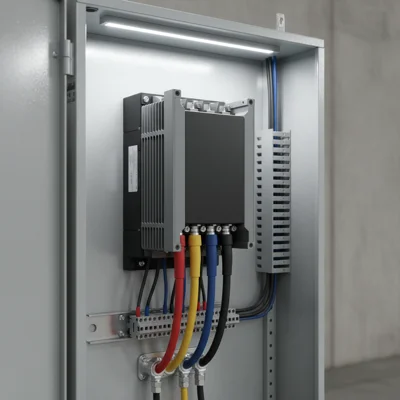
- Inadequate cooling. A VFD dissipates 2–4% of its rated power as heat. For a 30 kW drive that means 600–1,200 W. An electrical cabinet without forced ventilation will overheat quickly.
- Improper earthing. The motor-cable screen must be connected to the VFD enclosure and the motor frame at both ends using a 360° clamp, not a wire pigtail.